background image

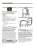
Rollover Crash—occupant seat belt pre-
tensioning, seat pre-tensioning, and side-roll air
bag at the proper time

Frontal Crash—no devices deployed

For vehicles with the RollTek system(s) and frontal
steering wheel air bag, device(s) deploy as follows:

Rollover Crash—occupant seat belt pre-
tensioning, seat pre-tensioning, and side-roll air
bag at the proper time

Frontal Crash—steering wheel air bag,
occupant seat belt pre-tensioning, seat pre-
tensioning, and the side-roll air bag at the
proper time

Inspection and Service

WARNING

Keep hands and tools away from the scissor
points under the seats.

The RollTek system contains components that
use combustible chemicals. Do not cut, drill,
braze, solder, weld, strike, or probe any part of
the RollTek system. Keep all liquids and
chemicals away from the RollTek components.

Do not attempt to service or modify the RollTek
system. Unintentional or improper deployment of
the RollTek system could cause severe bodily
injury or death. Contact an authorized

Freightliner service facility for all service and
maintenance.

IMPORTANT: The RollTek system must be
replaced after being activated. Damaged seat
belts and tethers, or seat belts and tethers that
were worn in an accident, must be replaced,
and their anchoring points must be checked.

The operational readiness of the RollTek system is
indicated by the SRS telltale on the driver display as
shown in

7.20.

Passenger Safety Telltales

Indicators (telltales) and Messages

Telltales and messages appear on the driver display.
The positions of the telltales vary, but most use
standard symbols.

The colors of telltales indicate the hazard level as
follows: red (warning), amber (caution), green
(normal function), blue (active status), grey (passive
status), white (informational).

The colors of messages indicate the hazard level as
follows: red (warning), amber (caution), grey
(informational).

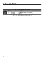
Telltales for passenger safety related features are
listed in

Table 7.1.

Every vehicle may not be

equipped with every feature.

Passenger Safety Telltale Lamps and Messages

Telltale

Color

Description

Related Message

Red

Unfastened Seat
Belt

Indicates the driver’s seat belt is unfastened.

When the system detects

that the parking brake is

off and the driver seat belt

is not fastened an audible

alert activates.

Amber

Supplemental
Restraint System
(SRS) Error

Indicates a malfunction has occurred in the
restraint system and restraint system
components may be triggered
unintentionally or may not deploy as
intended during an accident.

If the SRS telltale

appears, have the

restraint system

checked and repaired

immediately.

White

Left-Hand Door
Unlatched

Indicates the left-hand door on two door cab
is unlatched.

White

Right-Hand Door
Unlatched

Indicates the right-hand door on two door
cab is unlatched.

Seats and Restraints

7.14

Содержание PX113064S T 2016

Страница 1: ...how the vehicle is equipped such as the brand of engine if an air bag is installed or if the vehicle features a collision avoidance system etc GPS location data fault codes and other technical data ma...

Страница 2: ...ash injury or death should immediately be reported to Transport Canada and Daimler Trucks North America LLC If Transport Canada receives similar complaints it may open an investigation if it finds tha...

Страница 3: ...Assurance 5 1 6 Driver Assistance Features 6 1 7 Seats and Restraints 7 1 8 Cab Features 8 1 9 Electrical System 9 1 10 Vehicle Charging Operation and Shutdown 10 1 11 Brake Systems 11 1 12 Steering...

Страница 4: ......

Страница 5: ...ication Component Information Label 1 1 Component Gross Vehicle Weight Rating Label 1 1 Federal Motor Vehicle Safety Standard Label 1 1 Canada Certification Label 1 1 Emissions Labels 1 3 Customer Ass...

Страница 6: ...shown in Fig 1 4 It is applied on the interior edge for vehicles domiciled in the United States or manufactured for U S Canada operation Tractors built without a fifth wheel for U S operations will h...

Страница 7: ...20000 CHASSIS ENG TRANS 5TH WHEEL PARK BRAKE AXLE VIN 1FUJGBDV4GLZZ9999 1ST INT AXLE 5443 12000 5601 12350 6713 14800 6032 13300 6032 13300 6032 13300 9072 20000 9253 20400 11612 25600 10432 23000 90...

Страница 8: ...o nitrogen and water vapor GHG21 GHG14 17 components plus additional components including but not limited to transmissions axles predictive technologies idle reduction technologies for vocational vehi...

Страница 9: ...MLER TRUCKS NORTH AMERICA LLC Date of Manufacture 07 15 VIN NIV GVWR PNBV KG GVWR PNBV LBS GDTN2TRAC13C 23 587 52 000 VEH FAMILY CD 1FUJGBDV4GLZZ9999 EMISSION CONTROL IDENTIFIERS REGULATORY CLASS High...

Страница 10: ......

Страница 11: ...2 Vehicle Access Using the Key Fob 2 1 Opening the Doors 2 1 Entering and Exiting the Vehicle 2 2 Accessing the Back of the Cab 2 4 External Cab Access 2 5 Opening and Closing the Hood 2 5...

Страница 12: ...fobs programmed take the vehicle to an authorized Freightliner dealer or service facility Specifications This system consists of a key fob that uses a radio frequency link for communication between t...

Страница 13: ...vide secure footholds Follow the instructions on the warning labels as shown in Fig 2 4 when entering and exiting the cab Entering the Driver Side 1 Open the driver side door and place anything that y...

Страница 14: ...h your right hand 3 Step down on the bottom step with your right foot grasping the grab handles lower as you move down 4 Step to the ground with your left foot first Entering the Passenger Side 1 Open...

Страница 15: ...e back of cab access A grab handle is typically located on the back wall of the cab Steps are built into impact protection plates that surround the high voltage batteries and deck plates cover the top...

Страница 16: ...cessing the outside of the cab to clean the door s windows or windshield do not grab or hold onto the A pillar turning vane This feature is not designed as a steadying device or handhold Misuse of the...

Страница 17: ...sh with the cowl then secure the hood by engaging both hood hold down latches IMPORTANT Make sure that both hood hold down latches are fully engaged before operating the vehicle f880967 02 09 2021 A A...

Страница 18: ......

Страница 19: ...view 3 1 ICC5 Driver Display 3 2 Indicators Warnings and Messages 3 3 ICC5 Time and Date 3 12 ICC5 Instrument and Infotainment Screen Overview 3 13 ICC5 Touch Screen Operation 3 13 ICC5 Digital Instru...

Страница 20: ...io controls The B panel display is mounted above a menu of physical switches The Optical Finger Navigation OFN controls on the steering wheel can be used to navigate screens and feature settings The b...

Страница 21: ...ral the buttons in the left hand pod control the driver display features and the buttons in the right hand pod provide access to infotainment features Basic Driver Display Functions Alert Messages Ale...

Страница 22: ...rs telltales and warnings pop ups gauges appear on the driver display The positions of the indicators and warnings vary but most indicators use standard telltale symbols The colors of telltales and wa...

Страница 23: ...6 7 8 9 10 11 12 13 14 15 1 Current Speed 2 High Voltage Battery Status 3 Projected Range on Current State of Charge 4 High Voltage Batteries State of Charge 5 Speed of Vehicle Ahead 6 Distance to Veh...

Страница 24: ...attery problem has been detected f612076 05 03 2022 1 2 3 4 5 6 7 8 9 10 11 12 A A A Swipe a finger to the left or right over the light in the center switch pod button to page through screens when a m...

Страница 25: ...le in for service Red High Voltage Battery Failure A thermal event has been detected inside a high voltage battery Bring the vehicle to a safe stop apply the park brake turn the keyswitch to off and e...

Страница 26: ...is pressed the work brake is set or the park brake is set Red Park Brake Engaged Indicates the park brake is engaged Always engage the park brake before exiting the vehicle Red Low Brake Air Pressure...

Страница 27: ...EBS or the electronic air processing unit EAPU Stop the vehicle and call for service Table 3 2 Braking and Traction Telltale Lamps and Messages Detroit Assurance Telltale Lamps and Messages Telltale...

Страница 28: ...el Telltale Lamps and Messages Telltale Color Description Related Information Amber Low Coolant Level The battery coolant level is low OR The eDrive coolant level is low Fill the low cooling system re...

Страница 29: ...ill highlight which tire and what the issue is Amber Tire Pressure Monitoring System TPMS Caution At least one tire has high tire pressure or a TPMS battery is low and needs to be replaced The TPMS sc...

Страница 30: ...the left turn signal lamps are activated Blue High Beams On Indicates the high beam headlights are on Green Low Beams On Indicates the low beam headlights are on Blue Automatic High Beams On Indicates...

Страница 31: ...n Icons ICC5 Time and Date Time and Date Time and date are set automatically when the vehicle is equipped with a tachograph When a vehicle is equipped with a tachograph only the time zone can be chang...

Страница 32: ...ms can be edited by pressing on the pencil icon below the alarm tile To delete an alarm press on the edit pencil icon and choose Delete ICC5 Instrument and Infotainment Screen Overview ICC5 Infotainme...

Страница 33: ...uges shown in Fig 3 7 can be accessed under the Gauges menu on the infotainment display They are informational only The default order of the gauge display can be changed Pressing on an existing gauge...

Страница 34: ...essure until the foot brake pedal is depressed or the trailer brake is applied Suspension Air Pressure Gauge The suspension air pressure gauge registers the air pressure applied to the vehicle air sus...

Страница 35: ...ge See Fig 3 10 The option to Set Pressure is available on the tire pressure screen Selecting this option allows you to change default settings Selecting the temperature icon will show an image of the...

Страница 36: ...and ICC5 system settings Under the Cab menu this includes Digital Switches Lighting Settings Digital Switches Example of Digital Switch Icons and Layout Lane Departure Warning Active Traction Control...

Страница 37: ...is on Settings The settings menu allows you to choose system features such as display language units of measurement and sound levels Tap on the settings gear icon in the lower left hand corner of the...

Страница 38: ...etooth NFC Near Field Communication Wi Fi Active and authorized devices will have an options menu opened by selecting the three dots to the right of a device name to manage device call logs contacts a...

Страница 39: ...hicle rescan for devices 6 When a device is found the name of that device will appear on the screen in addition to the message My Device Was Not Found Select the device name 7 A pop up will appear ask...

Страница 40: ...Open the Phone menu The primary active phone s name should display in the upper left 2 Select the gear icon to access the setting for the phone The Options screen appears 3 Choose which of the followi...

Страница 41: ...ne to deauthorize The list of options available for that phone opens 5 Select Deauthorize The system asks for verification 6 Select Yes The phone is deauthorized Using a Mobile Phone General Phone Inf...

Страница 42: ...nding or Rejecting a Call There are two ways to end or reject a call Press the End Call button on the right hand OFN steering wheel pod Press the end call button on the infotainment screen Putting an...

Страница 43: ...elect the radio button for your choice of name format The format of the names in the phone contact list is changed Turning Off Synchronizing Phone Contacts Default system behavior is to have contacts...

Страница 44: ...orite Favorites 1 Select the star shortcut icon to open the Favorites menu 2 Press and hold on an individual favorite The Options menu for the favorite will open 3 Select Rename A keyboard will appear...

Страница 45: ...tation starts playing Searching for a SiriusXM Satellite Radio Station by Category 1 Select SiriusXM at the top of the Radio menu 2 Select the list icon at the bottom of the screen The SiriusXM menu o...

Страница 46: ...ns broadcasting official weather warnings watches advisories forecasts and other non weather related hazard information including news on natural disasters earthquakes avalanches floods environmental...

Страница 47: ...tar shortcut icon to open the Favorites menu Saved favorites are displayed 2 Press and hold on the icon for a favorite The Options menu appears 3 Select Move The selected favorite now has a checkmark...

Страница 48: ...ions Apple CarPlay can connect to the system via a USB2 cable or Bluetooth Android Auto Android Auto allows the driver to use an Android phone to make calls send and receive messages get information l...

Страница 49: ...functional Stalk Switch 4 1 Emergency High Voltage Disconnect Button 4 2 Exterior Lighting Controls 4 2 Dash Mounted Brake Controls 4 5 Horn Control 4 6 Suspension Controls 4 7 Trailer Controls 4 7 Fi...

Страница 50: ...s N Neutral R Reverse gear Mode Short press Switch between available driving modes Long press Switch between manual and automatic mode Gear Short pull on the lever Upshift single gear Short push on th...

Страница 51: ...A mark on the headlight switch stands for automatic If the headlight switch is set to automatic all exterior lights and the low beam headlights will illuminate when the outside light decreases to a pr...

Страница 52: ...turn signal lever is mounted on the left hand side of the steering column Pulling the turn signal lever up activates the right turn signal pushing it down activates the left turn signal f612025 03 21...

Страница 53: ...s the turn signal indicators in the ICU flash simultaneously when the hazard lamps are activated The switch will blink at the same rate that the hazard lamps flash Press the hazard warning light switc...

Страница 54: ...ase the tractor and trailer spring parking brakes Before the spring parking brakes can be released the air pressure in either air brake system must be at least 65 psi 448 kPa If the trailer is not equ...

Страница 55: ...pin during reduced traction situations In normal braking applications the standard air brake system is in effect If equipped pressing the ATC SPIN switch shown in Fig 4 14 shuts ATC off and allows dri...

Страница 56: ...gizes an optional circuit that allows the trailer electrical system to draw power for functions such as internal lights and battery charging for lift gates Press the top of the switch to activate the...

Страница 57: ...f611343 09 28 2016 AIR SLIDE SLIDE LOCK Fig 4 18 Fifth Wheel Air Slide Dash Switch Driver Controls 4 8...

Страница 58: ......

Страница 59: ...5 2 Detroit Assurance Tailgate Warning 5 5 Detroit Assurance Active Brake Assist 5 ABA5 5 5 Limitations of Detroit Assurance ABA5 and ACC 5 8 Detroit Assurance Lane Departure Warning LDW 5 12 Detroit...

Страница 60: ...osition the low beam headlights and vehicle exterior lights turn on when the RLS registers a low level of ambient light This could happen due to sunset fog smoke or any other event that decreases ligh...

Страница 61: ...switch pod as shown in Fig 5 4 contains adaptive cruise control ACC controls and access to Detroit Assurance settings via the quick access system settings button Detroit Assurance Adaptive Cruise Cont...

Страница 62: ...Fig 5 5 Adaptive Cruise Control Functions and Activation Conditions ACC controls the speed of the equipped vehicle to maintain a safe distance from a vehicle detected in front If ACC detects a vehicl...

Страница 63: ...control the message displayed allows the driver to use standard cruise control See Fig 5 7 f612040 07 21 2022 1 2 3 4 5 6 7 8 9 10 11 12 13 14 15 1 Current Speed 2 High Voltage Battery Status 3 Proje...

Страница 64: ...than 10 seconds at a distance that will be traversed in less than 2 6 seconds The system will also give warnings when ACC is active if the driver is overriding the distance control by pressing on the...

Страница 65: ...eople with a warning and emergency braking ABA5 can minimize the risk of a front end collision with a moving or stationary vehicle and pedestrians If ABA5 detects the risk of a front end collision it...

Страница 66: ...ial brake application ABA5 brakes the vehicle with 100 percent of the vehicle s maximum braking power The radio and or hands free system stays muted the warning beeping shifts to a continuous tone and...

Страница 67: ...Active Brake Assist 5 Limitations Condition and Illustration Description Cornering entering and exiting bends f040877 07 27 2022 The ability of ABA5 and ACC to react to vehicles on bends is limited A...

Страница 68: ...s changing lanes f040884 07 27 2022 The ability of ABA5 and ACC to detect and react to vehicles pulling into your lane without maintaining a safe distance is limited ABA5 and ACC may be slow to react...

Страница 69: ...27 2022 The ability of ABA5 and ACC to detect and react to a vehicle you are overtaking is limited When overtaking a vehicle ABA5 and ACC may unexpectedly issue warnings or brake your vehicle if you d...

Страница 70: ...detected vehicle even though there is a critical driving situation ACC may react to the vehicle turning off by accelerating unexpectedly Vehicles parked or broken down at the side of the road f040880...

Страница 71: ...em properly could result in personal injury and or death and severe property damage Safety Notes on Lane Departure Warning The system may be impaired or may not operate in the following situations The...

Страница 72: ...stem In addition to the visual warning when driving over lane markings unintentionally the volume of audio equipment like the radio and or hands free systems is muted and a rumble strip noise emits fr...

Страница 73: ...low visibility due to insufficient road illumination or due to snow rain fog smoke or heavy spray glare from oncoming traffic the sun or reflection from other vehicles when the road surface is wet the...

Страница 74: ...el LKA is on and actively steering Grey hands on steering wheel LKA is on but inactive due to glare snow bad lane lines etc Red hands on steering wheel auto stop is active Amber steering wheel with ex...

Страница 75: ...s and an acoustical warning starts to sound every five seconds If the driver does not return their hands to the steering wheel at 55 seconds the acoustical warning starts to sound every second If the...

Страница 76: ...display when auto stop has brought the vehicle to a standstill the auto stop telltale clears and a caution with the standstill override procedure appears on the driver display see Fig 5 20 Once auto s...

Страница 77: ...r and the first trailer False positive indications and warnings may occur with multiple trailers IMPORTANT SGA and ASGA1 are not designed to work with non ABS trailers or on trucks with lift axles In...

Страница 78: ...he sensors are dirty or SGA malfunctions a grey triangle alert icon appears on the driver display Objects in the monitoring range are not tracked when this occurs Before driving the vehicle ensure the...

Страница 79: ...Grey Caution Side Guard Assist Amber Caution Side Guard Assist Trailer Amber Caution Side Guard Assist Trailer Monitoring Deactivated Amber Warning Side Guard Assist Red Warning Side Guard Assist Tra...

Страница 80: ...ng range when a driver signals or steers to the right shown in Fig 5 30 an amber warning lamp activates f612095 07 21 2020 1 2 In a left hand drive vehicle the SGA activation state grey telltale appea...

Страница 81: ...tale appears on the driver display screen The red warning lamp stops flashing after a few seconds but stays on as long as there is a risk of a collision Activating or Deactivating Side Guard Assist If...

Страница 82: ...re is no steering wheel telltale Lane Keep Assist LKA is a component of Active Lane Assist ALA Grey Lane Keep Assist LKA on but inactive Lane Keep Assist is on but inactive Reasons for inactivity incl...

Страница 83: ...6 Driver Assistance Features Electronic Stability Control ESC 6 1 PasSmart 6 1 SafetyDirect by Bendix 6 2...

Страница 84: ...the ESC automatically reduces power and applies the brakes Yaw control is not active below approximately 6 mph 10 km h Roll stability control is not active below approximately 12 mph 20 km h At highe...

Страница 85: ...If equipped the SafetyDirect system uses the telematics systems of the vehicle and a Bendix 5G forward facing video camera shown in Fig 6 3 The Bendix camera records in color and can capture high qual...

Страница 86: ......

Страница 87: ...m High Back Seat 7 3 ISRI Basic High Back Seat 7 4 National High Back Seat 7 6 Sears Atlas II Deluxe High Back Seat 7 7 Sears Sentry High Back Seat 7 8 Seat Belts and Tether Belts 7 9 Steering Wheel A...

Страница 88: ...each the steering wheel with angled arms NOTICE Do not install seat covers on seats with heating and ventilation Do not cover the seat with blankets clothing or pillows Blocking the air flow through t...

Страница 89: ...back and side support areas of the seat Making changes to a driver s sitting position from time to time helps prevent driver fatigue and improves posture 3 1 Lumbar Lower Back Support Press the forwar...

Страница 90: ...ver and add or reduce weight on the front area of the seat cushion to move it into one of three positions Release the lever to lock the seat into position The tilt of the seat along with the tilt of t...

Страница 91: ...length of the seat cushion until there is space for three fingers between the cushion s front edge and the back the driver s knee This helps to help improve circulation in the lower legs 7 Fore Aft Sl...

Страница 92: ...ves up to 2 3 8 inches 60 mm in 3 8 inch 10 mm increments Releasing the lever locks the cushion in place Adjust the length of the seat cushion until there is space for three fingers between the cushio...

Страница 93: ...er switch to the on position The Backcycler will inflate and deflate the lumbar area sections of the seat in 40 second cycles Let the BackCycler go through two or three cycles before turning it off an...

Страница 94: ...the arm as you listen for clicks Each click represents one of seven armrest positions Stop when the armrest is high enough to support your forearm in a horizontal position Each armrest can be adjuste...

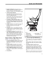
Страница 95: ...on Release the handle to lock the seat in place Three positions are available Sears Sentry High Back Seat See Fig 7 12 for seat adjustment controls 1 Seat Tilt and Extension Knob Rotate the knob clock...

Страница 96: ...int system is required review and comply with applicable state and local laws Any child restraint used must comply with Federal Motor Vehicle Safety Standard 213 Child Restraint Systems When providing...

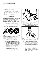
Страница 97: ...nt of slack into the seat belt resulting in a more comfortable ride Fastening the Seat Belt 1 If needed adjust the seat to achieve the proper driving position 2 Slowly pull the link end of the seat be...

Страница 98: ...shown in Fig 7 18 While holding the belt slack press the Komfort Latch lever up as shown in Fig 7 19 Allow no more than 1 inch 2 5 cm of slack as more slack can significantly reduce the seat belt eff...

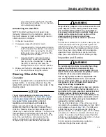
Страница 99: ...teering wheel or between you and the steering wheel Any such objects may cause harm during an accident Keep your hands on the sides and lower portion of the steering wheel Failure to follow these inst...

Страница 100: ...s the seat suspension moving the occupant down and away from the steering wheel and ceiling As the seat is pulled down to its lowest position the side roll air bag deploys from the outboard side of th...

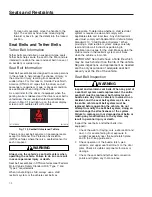
Страница 101: ...readiness of the RollTek system is indicated by the SRS telltale on the driver display as shown in 7 20 Passenger Safety Telltales Indicators telltales and Messages Telltales and messages appear on th...

Страница 102: ...e Lamps and Messages Telltale Color Description Related Message White Both Doors Unlatched Indicates both doors on a two door cab are unlatched Table 7 1 Passenger Safety Telltale Lamps and Messages S...

Страница 103: ...b Features Cab Amenities 8 1 Keyswitch 8 2 Adjustable Steering Column Controls 8 3 Interior Lighting Controls 8 3 Windows 8 4 Mirrors 8 4 Windshield Wiper and Washer Controls 8 5 Cab Climate Controls...

Страница 104: ...controls and a shortcut switch to the digital radio screens Other radio controls such as choosing an audio source or radio station or saving a station as a favorite can be done through the infotainmen...

Страница 105: ...is vertical The key can be inserted and removed only in the OFF position The following functions are operable when the keyswitch is in the OFF position regardless of whether a key is inserted low bea...

Страница 106: ...el can be adjusted up and down and tilted forward and backward Once the wheel is in the desired position lock the position by pushing the lever toward the column until it is parallel to the column and...

Страница 107: ...windows are standard on eCascadia vehicles The passenger s door has a switch mounted in the top of the door that controls the passenger side power window The driver s door has two switches mounted in...

Страница 108: ...tate the switch to increase the wiper speed through the two intermittent speeds the continuous low speed to the continuous high speed Rotate the switch down to slow the wipers Rotate the switch all th...

Страница 109: ...to initiate a single swipe of the windshield wipers without activating the washer pump To activate the windshield washer system press and hold the washer switch After a short delay the pump sprays win...

Страница 110: ...During extreme climate conditions or when driving through dusty or smoky conditions the partial recirculation mode can be overridden by pressing the recirculation button twice to switch back to full r...

Страница 111: ...hrough the floor outlets Floor Defrost Mode Directs the airflow equally to the floor outlets and the defrost outlets Defrost Mode Directs all airflow through the defrost outlets All Mode Directs the a...

Страница 112: ......

Страница 113: ...9 Electrical System Electric Vehicle Overview 9 1 Low Voltage Battery Disconnect Procedure 9 5 Smart Battery Shut Off Switch 9 5 Electric Vehicle Power Distribution 9 5 Powernet Management 9 6...

Страница 114: ...les to get energized and be functional In these systems it is desirable to protect 12V and 24V components outputs inputs wires and cables from possible over current events The electric vehicle power d...

Страница 115: ...ain level and is able to maintain a constant heating element temperature during load and supply voltage changes For this reason the risk of the heating element s overheating or catching fire is minima...

Страница 116: ...entation control unit ICU self check The majority of electrical and electronic issues on the vehicle will have an associated fault code which will be displayed on the ICU If the ICU receives active fa...

Страница 117: ...ntrol Unit DCL DC DC Converter RDF RDF Radar Front End DCMD Door Control Module Driver SAS Steering Angle Sensor DCMP Door Control Module Passenger SSAM Single Signal Detect and Actuation Module EAPU...

Страница 118: ...battery and the battery cable access box BCA Where pressing the eStop button prevents the high voltage system from turning on turning off the smart battery shut off switch disables the low voltage pow...

Страница 119: ...Electrical and Electronic Components Pass Through Bulkhead Connector The pass through bulkhead connector is where the interior dash harness connects to the exterior chassis harness This provides a di...

Страница 120: ...loads to avoid unnecessary cycling when battery voltage is close to shutdown thresholds Loads disconnected by the PLVD will reconnect when all of the following conditions are met keyswitch ON batterie...

Страница 121: ...f547313 08 14 2020 Fig 9 8 Example Fuse Labeling on BCA Cover f547312 08 14 2020 Fig 9 9 EVDM Inside Cover Map of Fuses and Relays Electrical System 9 8...

Страница 122: ......

Страница 123: ...Charging Operation and Shutdown Charging the Vehicle 10 1 Operating the Vehicle 10 6 Vehicle Protection Warnings 10 11 Vehicle Shutdown 10 16 High Voltage Battery Deactivation 10 16 ePowertrain Tellt...

Страница 124: ...e the charge port inlet plugs shown in Fig 10 3 If the inlets are protected with doors as shown in Fig 10 2 press the latches in the direction of the arrows to open the doors 5 Verify the inlet is unl...

Страница 125: ...is fully engaged f547632b 06 21 2022 1 3 2 4 6 5 1 Inlet Lock Lamp 2 Inlet Status Lamp 3 Charging Status Lamp 4 Battery Charging Lamp 5 Inlet Door Plugs 6 Stop Charging Button Fig 10 3 Charge Port wi...

Страница 126: ...cle inlet 10 Remove the charging coupler from the vehicle inlet 10 1 If the batteries are fully charged press the coupler s top latch button and remove the coupler from the inlet 10 2 If the batteries...

Страница 127: ...ual Ports Pulsing Red and Green One inlet has an error the other is functioning Unplug the couplers and plug them in again If the error persists have the charger couplers and or vehicle inlets checked...

Страница 128: ...and two plug telltales appear on the driver display one for each coupler If a vehicle is charging in single port mode and a second coupler is inserted the charging current demand on the first port is...

Страница 129: ...e for the departure time can also be specified 4 Select the back arrow to return to the Charge Battery screen NOTE The lowest accepted charge limit is 50 percent 5 Select Charging Limit When on the sc...

Страница 130: ...ART position for a minimum of second After the vehicle has started the READY telltale shown in Fig 10 13 appears at the bottom of the power gauge on the driver s display NOTE If the vehicle did not st...

Страница 131: ...with a green line capped with a caret on the power gauge See Fig 10 14 item 2 Economy Mode To encourage efficient driving behavior and reduce energy consumption the default driving mode is economy In...

Страница 132: ...ost power is available the boost status meter appears grey When boost mode is active the boost status meter displays the power use as an amber line Normal Operation The needle on the driver display po...

Страница 133: ...heavy usage of the friction brakes Use regenerative braking whenever possible Regenerative braking increases range by charging the high voltage batteries Lower the vehicle speed just before the crest...

Страница 134: ...the vehicle and 1 representing fully charged high voltage batteries The vehicle s estimated range appears above the SOC gauge This distance is based on the high voltage batteries SOC as well as the ve...

Страница 135: ...before the third warning shown in Fig 10 20 appears on the driver display screen At this point the amber caret on the power gauge is at 0 percent and driving is not allowed Have the vehicle towed to a...

Страница 136: ...g the driver to take the vehicle in for service shown in Fig 10 26 to a warning that results in the vehicle shutting down shown in Fig 10 27 All windows must be acknowledge by the driver eMotor Oversp...

Страница 137: ...ttery cautions and warnings The high voltage battery problem telltale shown in Fig 10 30 appears in the dynamic telltale portion of the driver display screen when a non critical high voltage battery f...

Страница 138: ...eStop button and exit the cab within five minutes Once in a safe location call emergency services For more information on this system see Chapter 19 Combustible Gas Detection System If the explosive...

Страница 139: ...top button located on the dash as shown in Fig 10 36 A lock can be inserted through the eStop button guard to keep the button depressed 3 In addition for the use of emergency responders a cut through...

Страница 140: ...nd 19 Telltale Color Description Related Messages Blue Charger Connected to Vehicle A flashing telltale indicates the vehicle is actively charging Solid illumination indicates the desired SOC has been...

Страница 141: ...ault such as one of the high voltage batteries going offline Take the vehicle in for service Red High Voltage Battery Failure A thermal event has been detected inside a high voltage battery Bring the...

Страница 142: ......

Страница 143: ...rative Braking 11 1 Energy Waste Mode 11 2 Descent Control 11 2 Hill Start Aid 11 3 Hold Function 11 3 Air Brake System 11 4 ZF Antilock Braking System 11 7 Automatic Traction Control 11 8 Brake and T...

Страница 144: ...death To activate regenerative braking with the right hand stalk switch select position one through three as shown in Fig 11 1 When a regenerative braking level is selected the regenerative braking te...

Страница 145: ...A suggests setting the stalk switch to high to allow the driver to regulate the amount of regenerative braking through modulating the pressure on the accelerator pedal When the driver lifts their foot...

Страница 146: ...is inactive the HSA OFF telltale shown in Fig 11 6 flashes on the driver display screen To turn hill start aid on again press the HSA OFF switch or cycle the vehicle keyswitch If the hill start aid d...

Страница 147: ...front brakes backed off or disconnected Backing off or disconnecting the front brakes will not improve vehicle handling and may lead to loss of vehicle control resulting in property damage or personal...

Страница 148: ...both the primary and secondary systems Monitor the air pressure system using the dual system air pressure gauge and the low air pressure telltale and buzzer The warning telltale and buzzer shut off wh...

Страница 149: ...e To do so could damage the brakes Allow hot brakes to cool before using the spring parking brakes Do not use the spring parking brakes during freezing temperatures if the service brakes are wet To do...

Страница 150: ...the electrical circuitry The ZF Antilock Braking System combines one front axle control channel with one rear axle control channel to form one control circuit For example the sensor and modulator valv...

Страница 151: ...n telltale shown in 11 15 flashes and an alert is shown on the driver display Pressing the ATC SPIN switch shown in Fig 11 16 deactivates ATC and allows drive wheel spin When ATC is off an ATC deactiv...

Страница 152: ...e or rapidly apply and release the brake pedal Red Park Brake Engaged Indicates the park brake is engaged Always engage the park brake before exiting the vehicle Red Low Brake Air Pressure Indicates a...

Страница 153: ...gain to active ATC Amber Brake System Caution A solid telltale indicates a fault or malfunction with the Antilock Braking System Electronic Braking System ABS EBS or the electronic air processing unit...

Страница 154: ......

Страница 155: ...12 Steering System Power Steering System 12 1...

Страница 156: ...adaptive power steering system results in the red telltale shown in Fig 12 1 An error with the electro hydraulic power steering system results in the display of this telltale in yellow as shown in Fig...

Страница 157: ...rmance If this occurs the power steering malfunction window as shown in Fig 12 6 appears on the driver display along with the yellow electro hydraulic power steering error telltale f612045 03 28 2022...

Страница 158: ......

Страница 159: ...13 eAxle eAxle 2 Speed Transmission 13 1...

Страница 160: ...2 speed transmission mode on the driver display changes to neutral If the vehicle is left in drive or reverse and the driver turns the keyswitch to off or requests the vehicle power down by other mean...

Страница 161: ...age the differential and or lead f611949 09 13 2021 DIFF LOCK Fig 13 2 DCDL Dash Switch f611982 11 30 2021 1 10 11 2 3 4 5 6 7 8 9 1 Menu Back 2 Menu Forward 3 Gauges Menu 4 Cab Menu 5 Axles Menu 6 Po...

Страница 162: ...amber and the bubble on the infotainment display illuminates solid yellow when the lock is engaged WARNING Be especially careful when driving under slippery conditions with the differential locked Tho...

Страница 163: ...14 Fifth Wheels Fifth Wheel Lubrication 14 1 Fifth Wheel Coupling 14 1 Fifth Wheel Uncoupling 14 8 Fifth Wheel Slide 14 10...

Страница 164: ...e any fifth wheel that fails to operate properly Doing so may cause loss of vehicle control possibly resulting in severe personal injury or death Fifth wheel coupling is activated with the lock contro...

Страница 165: ...personal injury or death NOTICE Attempting to couple at the wrong height may cause improper coupling which could result in damage to the fifth wheel or kingpin 7 Adjust the trailer height if required...

Страница 166: ...ke care to prevent dirt or foreign material from entering the air system lines NOTICE Always make sure the connection hanger keeps the trailer air hoses and electrical cables positioned so that they d...

Страница 167: ...le at the wrong height may cause improper coupling which could result in damage to the fifth wheel or kingpin 6 Adjust the trailer height if required For a standard fifth wheel plate the trailer shoul...

Страница 168: ...he trailer to disconnect possibly resulting in serious personal injury or death 9 Perform a coupling inspection 9 1 Verifying a Holland FW35 fifth wheel is locked Verify that there is no gap between t...

Страница 169: ...ance between the kingpin and the fifth wheel jaws by moving the tractor forward and backward against the locked kingpin If slack is present uncouple the trailer and have the fifth wheel inspected and...

Страница 170: ...ndle should abut the casting as shown in Fig 14 19 There should be no gap between the trailer and the fifth wheel 8 Release the tractor parking brakes and test for kingpin lockup by slowly moving the...

Страница 171: ...lock control handle to the unlocked position as shown in Fig 14 3 7 2 Holland FW35 Pull out the release handle as shown in Fig 14 8 7 3 Holland FWAL Slide the handle forward to move the front notch o...

Страница 172: ...al cable Plug the air lines to prevent dirt or foreign material from entering the lines Air Activated Kingpin Unlock NOTE The kingpin release will not activate if the vehicle is moving the parking bra...

Страница 173: ...Vehicle Identification chapter for the location of these labels on your vehicle The desired load on the axle is no less than 80 percent of the maximum axle weight rating but in no instances should the...

Страница 174: ...nents and that the front of the trailer will not come in contact with the rear of the cab or other components if they extend beyond the rear of the cab 5 Apply the tractor parking brakes WARNING Check...

Страница 175: ...king wedges to fully lock Further verify that the plungers have engaged by tugging the tractor forward while the trailer brakes are locked and the wheels are chocked 09 10 2010 f311131 A B A Unlocked...

Страница 176: ......

Страница 177: ...15 Headlight Aiming Before Checking the Headlight Aim 15 1 Checking the Aim of the Headlights 15 1 Adjusting the Aim of a Headlight 15 3...

Страница 178: ...ke Chock the tires 2 Each headlight has a height adjusting dot on the lens as shown in Fig 15 1 Measure the distance from the ground to the height adjusting dot on each headlight See Fig 15 2 item A M...

Страница 179: ...should appear 1 Screen or Wall 2 Center of Right Hand Headlight Projection 3 Center of Left Hand Headlight Projection Fig 15 2 Headlight Aiming Screen Wall f546265b 10 04 2021 A 1 2 3 A Measurement 2...

Страница 180: ...e power tools to adjust headlight aim Doing so will strip or break the adjusting screw The adjusting screw is located on the bottom of the headlight assembly accessible from inside the wheel well when...

Страница 181: ...aning and Disinfecting Cab Surfaces 16 1 Cleaning the Cab Floor 16 2 Cleaning the Upholstery 16 2 Washing and Polishing the Cab 16 4 Care of Exterior Lights 16 4 Caring for External Chrome Components...

Страница 182: ...ble or ready to use quaternary ammonium based disinfectant on vehicle interior and exterior surfaces IMPORTANT Follow the manufacturer s instructions for using a disinfectant as these vary by product...

Страница 183: ...hypochlorous acid silicone Cleaning the Cab Floor Do not pressure wash the cab floor in an electric vehicle The supplemental restraint system SRS crash detection equipment located behind the driver s...

Страница 184: ...dered cleaners such as those used for sinks and tiles are abrasive and must be used with caution as they can scratch the vinyl or give it a permanent dull appearance Chewing Gum Harden the gum with an...

Страница 185: ...oking New To extend the life of your vehicle s finish follow these guidelines Avoid washing your vehicle in the hot sun Always use water After the cab is completely washed dry it with a towel or chamo...

Страница 186: ...rgent may also be used Sponge gently then rinse If necessary use a non abrasive chrome cleaner to remove stubborn rust or other material Do not use steel wool To help protect the chrome after cleaning...

Страница 187: ...17 Pre and Post Trip Checklists Periodic Inspections and Maintenance General Information 17 1 Checklists 17 1 Fluids Added 17 2...

Страница 188: ...amine tire condition 3 Check tire inflation 4 Examine and clean rims and wheel components Inspection of Wheels and Tires Done 5 Inspect wheel bearing oil seals and lubrication levels 6 Check mud flaps...

Страница 189: ...ck thickness of brake linings eAxle Done 1 Inspect rear pads 2 Inspect bolts on mounting brackets Mid Frame Area Done 1 Drain brake system air reservoirs on vehicles without automatic drain valves 2 I...

Страница 190: ......

Страница 191: ...Post Trip Inspections and Maintenance Safety Precautions 18 1 Daily Pre Trip Inspections and Maintenance 18 1 Weekly Post Trip Inspections and Maintenance 18 8 Monthly Post Trip Inspections and Mainte...

Страница 192: ...nd maintenance procedures detailed in this chapter are not all inclusive Refer to other component and body manufacturers instructions for specific inspection and maintenance instructions as well as lo...

Страница 193: ...ent tires must meet or have less rolling resistance than the originally installed tires in order to maintain compliance with greenhouse gas and fuel efficiency regulations Contact your tire manufactur...

Страница 194: ...b cap See Group 35 of the eCascadia Maintenance Manual for recommended lubricants 6 Check that mud flaps are undamaged and hang 10 inches 25 4 cm or less from the ground Mid Frame Area Inspection WARN...

Страница 195: ...8 Close the hood Cab Inspection 1 With the key in the OFF position check the air pressure warning system NOTE The low air warning buzzer only works when the park brake is released The low air warning...

Страница 196: ...application and observe the pressure drop on the primary air gauge If pressure drops more than 25 psi 172 kPa eliminate any leaks before operating the vehicle Maximum Allowable Air Leakage Descriptio...

Страница 197: ...11 1 Make sure the parking brake is set NOTE Vehicle factory settings will have groups of lamps activate sequentially up to 100 times or until manually stopped f547817 04 28 2022 7 1 1 2 3 4 5 6 8 1...

Страница 198: ...s When any part of a seat belt system needs replacement the entire seat belt must be replaced both retractor and buckle side Any time a vehicle is involved in an accident and the seat belt system was...

Страница 199: ...rain tray installed at the base of the windshield Ensure that the seal on the forward edge of the rain tray is in good condition 3 2 Inspect the drain hoses installed on the rain tray Both hoses shoul...

Страница 200: ...ause injury NOTICE If the water drained from the air reservoirs is cloudy or oily it may indicate a problem with the compressor If oil is allowed to contaminate the air dryer it will not remove the wa...

Страница 201: ...tage batteries WARNING Battery posts terminals and related accessories contain lead and lead compounds chemicals known to the State of California to cause cancer and reproductive harm To prevent possi...

Страница 202: ......

Страница 203: ...19 1 In Case of an Under Inflated or Flat Tire 19 2 Jump Starting an eCascadia 19 2 Towing the Vehicle 19 4 Lifting and Lowering the Vehicle 19 8 Combustible Gas Detection System 19 9 In Case of a Hi...

Страница 204: ...voltage system and if equipped deploys the SRS air bag Activating the Hazard Warning Lights The hazard warning light switch is located on the dash as shown in Fig 19 2 The hazard warning lights can be...

Страница 205: ...ondition that may result in damage to the vehicle Driving with under inflated tires may permanently damage the tires and increases the likelihood of tire failure Pull off the road to a safe location a...

Страница 206: ...se posts instead of the batteries When using jumper cables follow the instructions below 1 Apply the parking brakes and turn off the lights and all other electrical devices 2 Open the hood NOTICE Alwa...

Страница 207: ...f the combined weight of both vehicles is more than the sum of the gross axle weight ratings GAWR of the towing vehicle Otherwise brake capacity will be inadequate which could result in personal injur...

Страница 208: ...umper Pull the tow loops to ensure they are securely engaged in the tow loop receivers 4 Lower the stinger assembly so that it is level and approximately 1 inch 0 3 cm off the ground Back the tow truc...

Страница 209: ...es WARNING Before towing an eCascadia all rear axle shafts must be removed Failure to remove the axle shafts will result in damage to the axle vehicle and the driven electric motors may cause inductio...

Страница 210: ...Remove the tow cables from the tow loops and retract the recovery boom See Fig 19 14 13 Remove the tow loops from the bumper 14 Connect the air and electrical supply lines from the tow truck to the t...

Страница 211: ...e to move or shift on the jack stands as air pressure drains from the system this could cause the vehicle to fall resulting in damage to the vehicle serious injury or death 2 Exhaust all air from the...

Страница 212: ...es only when necessary and do not leave them disconnected for extended periods of time A USA Pro Shoreline multizone combustible gas detection system is standard equipment on an eCascadia The system i...

Страница 213: ...panel of the cab as shown in Fig 19 21 WARNING Immediately bring the vehicle to a safe stop when the buzzer alarm sounds and the lower red Significant LED illuminates Apply the park brake turn off the...

Страница 214: ...n standing next to the B pillar and looking up through the side windows Trace Gas Levels Detected A steady yellow Trace Gas LED indicates a gas concentration greater than 20 of the LEL for that gas ha...

Страница 215: ...fifteen minutes If you observe smoke move a safe distance from the vehicle fifty to one hundred feet if possible Avoid inhaling the smoke When in a safe location call emergency services If no smoke i...

Страница 216: ...towed vehicle indoors If there is no smoke Pull over into a safe location Turn off the ignition set the park brake and exit the vehicle If applicable call a supervisor for assistance Observe the vehic...

Страница 217: ...sounds The green System Normal LED goes out Quickly bring the vehicle to a safe stop Apply the park brake turn off the ignition exit the cab and call emergency responders Red Upper Bar illuminated Dan...

Страница 218: ...trol Module Do not attempt to reset the system until the gas has cleared and if called emergency personnel have declared the vehicle safe Silence If an alarm has been activated by cleaning chemicals o...

Страница 219: ...from a high voltage battery assume that it is heating Leave the area Avoid breathing in the smoke Breathing in the smoke could result in severe personal injury NOTICE If smoke or flames are coming fr...

Страница 220: ...of fire in heavy and medium duty trucks is rare In addition Federal Motor Vehicle Safety Standard 302 limits the flammability of specified materials used inside the cab However most materials can bur...

Страница 221: ...cable cut point is located below and toward the back of each cab door a right hand cable cut point is shown in Fig 19 24 Each cable cut point is marked with a yellow first responder cable cut tag deco...

Страница 222: ......

Страница 223: ...20 Emissions Information Noise Emissions 20 1 Greenhouse Gas Emissions 20 1...

Страница 224: ...icle is in reverse If the vehicle has been ordered with a backup alarm this beep will sound like an electric alarm clock If the vehicle is ordered with no backup alarm the reverse beep alert will soun...

Страница 225: ...21 Telematics Information Telematics Information and Terms of Use 21 1 Frequency Bands and Maximum Transmission Output 21 3...

Страница 226: ...s information and similar information we receive from other DTNA vehicles To make your vehicle safer and to improve its performance Depending on the type of devices installed on your vehicle DTNA may...

Страница 227: ...matics information will not be hacked deleted intercepted or altered DTNA will also require other parties to whom telematics information is disclosed to take reasonable steps to protect the telematics...

Страница 228: ...2 MHz Receive only Table 21 1 Frequency Bands and Maximum Transmission Output The Common Telematics Platform The Detroit Connect Platform is the connectivity module of Daimler Trucks North America It...

Страница 229: ......

Страница 230: ...Pre Trip Inspection Checklists 17 1 Monthly Post Trip Inspection Checklists 17 2 Weekly Post Trip Inspection Checklist 17 1 Cleaning and Disinfecting Cab Surfaces 16 1 Cleaning and Disinfecting Chemi...

Страница 231: ...5 22 General Information 5 18 Safety Information 5 19 Sensor Monitoring Range 5 19 SGA Indicator Lamps 5 20 Side Guard Assist Activation Conditions 5 20 Warnings for Moving Objects 5 21 Subject Page W...

Страница 232: ...ctric Horn 4 6 Subject Page I ICC5 Digital Instruments 3 14 Active Driver Alerts 3 17 Application Air Pressure Gauge 3 15 Axles 3 16 Base ICC5 A Panel Gauges 3 15 Batter and eDrive Coolant Levels 3 15...

Страница 233: ...Monthly Post Trip Inspections and Maintenance 18 8 Brake Component Inspection 18 8 Subject Page eAxle Inspection 18 9 Front Box Inspection and Adjustments 18 9 Mid Frame Area Inspection 18 9 Multifunc...

Страница 234: ...formation and Who We Share it With 21 2 Your Consent 21 2 Your Rights 21 2 Towing the Vehicle 19 4 Subject Page Front Towing Hookup With Removable Tow Loops 19 4 Rear Towing 19 8 Use of Tow Loops 19 4...

Страница 235: ...Subject Page Wiper Controls 8 5 Wipers and the Rain Light Sensor 8 6 Z ZF Antilock Braking System 11 7 Trailer ABS Compatibility 11 7 Index I 6...

Страница 236: ......
Отзывы: