B. Signal Coupling for Analog Input 3 and Analog Input 4.
1) Input Resistor
The IO Slave DIs have always provided an internal 10Kohm resistor pull-up to the radio’s 3.3V
logic supply. With new firmware 2.65IO in the FGRIO-S, or 9.7 in the FGR2-IOS, the resistor
can also be commanded (in the FGRIO Setup menu) to pull down to GND or “float” uncon-
nected. As will be shown, these options are useful for connection of analog inputs.
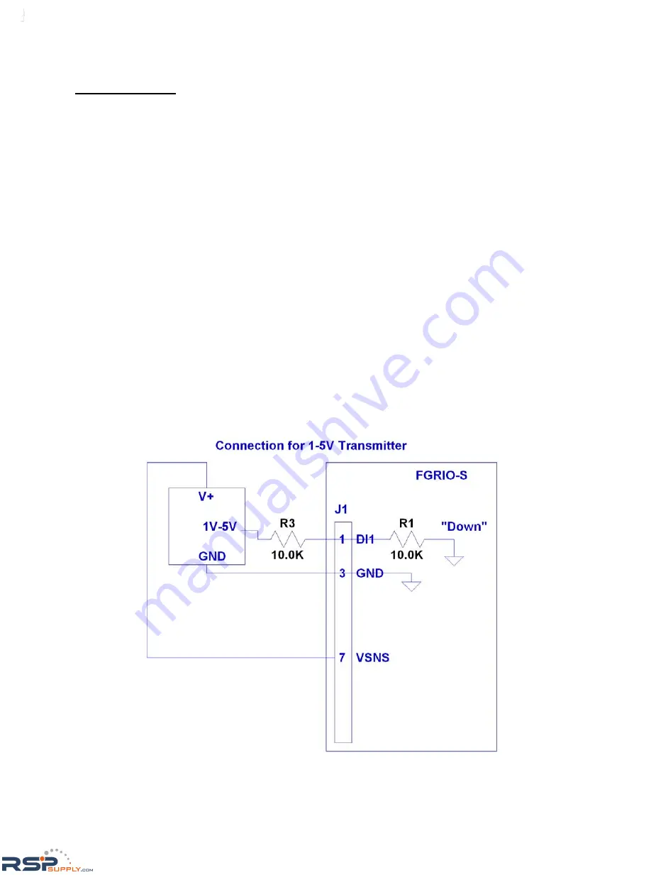
2) Signal Level Reduction.
As stated above, the DI does not have sufficient voltage range for direct connection to typical
transducer outputs, so the input must be restricted. For signal replication, it is assumed the input
signal level will be halved, and the measured value sent to the FGRIO-M doubled, to achieve an
overall 1:1 signal reproduction.
3) VSNS Sensor Power
The switched voltage source at screw terminal #7 is designed to drive only two 4-20mA trans-
mitters to full scale. Voltage output (1-5V) transmitters usually consume less current and may
allow up to 4 to be switched.
Below are two diagrams showing the connection of a 1-5V sensor to Analog Input 3: (Figures 23
and 24)
Installation (cont.)
Figure 23
RSPSupply - 1-888-532-2706 - www.RSPSupply.com
http://www.RSPSupply.com/p-20028-FreeWave-FGR2-IO-IOE-Radio-Enclosed-900-MHz-I/O-Slave-Radio.aspx


