


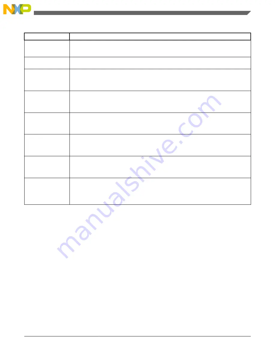
Table 15-1. Power modes (continued)
Mode
Description
VLPW
The core clock is gated off. The system, bus, and flash clocks continue to operate, although their
maximum frequency is restricted. See the Power Management chapter for details on the maximum
allowable frequencies.
VLPS
The core clock is gated off. System clocks to other masters and bus clocks are gated off after all
stop acknowledge signals from supporting peripherals are valid.
LLS3
The core clock is gated off. System clocks to other masters and bus clocks are gated off after all
stop acknowledge signals from supporting peripherals are valid. The MCU is placed in a low
leakage mode by reducing the voltage to internal logic. All system RAM contents, internal logic and
I/O states are retained.
LLS2
The core clock is gated off. System clocks to other masters and bus clocks are gated off after all
stop acknowledge signals from supporting peripherals are valid. The MCU is placed in a low
leakage mode by reducing voltage to internal logic and powering down the system RAM2 partition.
The system RAM1 partition, internal logic and I/O states are retained.
VLLS3
The core clock is gated off. System clocks to other masters and bus clocks are gated off after all
stop acknowledge signals from supporting peripherals are valid. The MCU is placed in a low
leakage mode by powering down the internal logic. All system RAM contents are retained and I/O
states are held. Internal logic states are not retained.
VLLS2
The core clock is gated off. System clocks to other masters and bus clocks are gated off after all
stop acknowledge signals from supporting peripherals are valid. The MCU is placed in a low
leakage mode by powering down the internal logic and the system RAM2 partition. The system
RAM1 partition contents are retained in this mode. Internal logic states are not retained.
VLLS1
The core clock is gated off. System clocks to other masters and bus clocks are gated off after all
stop acknowledge signals from supporting peripherals are valid. The MCU is placed in a low
leakage mode by powering down the internal logic and all system RAM. I/O states are held. Internal
logic states are not retained.
VLLS0
The core clock is gated off. System clocks to other masters and bus clocks are gated off after all
stop acknowledge signals from supporting peripherals are valid. The MCU is placed in a low
leakage mode by powering down the internal logic and all system RAM. I/O states are held. Internal
logic states are not retained. The 1kHz LPO clock is disabled and the power on reset (POR) circuit
can be optionally enabled using STOPCTRL[PORPO].
1. See the devices' chip configuration details for the size and location of the system RAM partitions.
2. See the devices' chip configuration details for the size and location of the system RAM partitions.
15.3 Memory map and register descriptions
Information about the registers related to the system mode controller can be found here.
Different SMC registers reset on different reset types. Each register's description provides
details. For more information about the types of reset on this chip, refer to the Reset
section details.
NOTE
The SMC registers can be written only in supervisor mode.
Write accesses in user mode are blocked and will result in a bus
error.
Chapter 15 System Mode Controller (SMC)
K22F Sub-Family Reference Manual , Rev. 3, 7/2014
Freescale Semiconductor, Inc.
341
Содержание MK22FN256VDC12
Страница 2: ...K22F Sub Family Reference Manual Rev 3 7 2014 2 Freescale Semiconductor Inc...
Страница 136: ...Human machine interfaces K22F Sub Family Reference Manual Rev 3 7 2014 136 Freescale Semiconductor Inc...
Страница 164: ...Module clocks K22F Sub Family Reference Manual Rev 3 7 2014 164 Freescale Semiconductor Inc...
Страница 246: ...Functional description K22F Sub Family Reference Manual Rev 3 7 2014 246 Freescale Semiconductor Inc...
Страница 328: ...Kinetis Flashloader Status Error Codes K22F Sub Family Reference Manual Rev 3 7 2014 328 Freescale Semiconductor Inc...
Страница 360: ...Functional description K22F Sub Family Reference Manual Rev 3 7 2014 360 Freescale Semiconductor Inc...
Страница 388: ...Functional description K22F Sub Family Reference Manual Rev 3 7 2014 388 Freescale Semiconductor Inc...
Страница 402: ...Initialization application information K22F Sub Family Reference Manual Rev 3 7 2014 402 Freescale Semiconductor Inc...
Страница 500: ...Initialization application information K22F Sub Family Reference Manual Rev 3 7 2014 500 Freescale Semiconductor Inc...
Страница 670: ...Flash memory map for EzPort access K22F Sub Family Reference Manual Rev 3 7 2014 670 Freescale Semiconductor Inc...
Страница 680: ...Functional description K22F Sub Family Reference Manual Rev 3 7 2014 680 Freescale Semiconductor Inc...
Страница 744: ...Application information K22F Sub Family Reference Manual Rev 3 7 2014 744 Freescale Semiconductor Inc...
Страница 784: ...Functional description K22F Sub Family Reference Manual Rev 3 7 2014 784 Freescale Semiconductor Inc...
Страница 794: ...Initialization Application Information K22F Sub Family Reference Manual Rev 3 7 2014 794 Freescale Semiconductor Inc...
Страница 960: ...Example configuration for chained timers K22F Sub Family Reference Manual Rev 3 7 2014 960 Freescale Semiconductor Inc...
Страница 1036: ...Device mode IRC48 operation K22F Sub Family Reference Manual Rev 3 7 2014 1036 Freescale Semiconductor Inc...
Страница 1040: ...USB Voltage Regulator Module Signal Descriptions K22F Sub Family Reference Manual Rev 3 7 2014 1040 Freescale Semiconductor Inc...
Страница 1094: ...Initialization application information K22F Sub Family Reference Manual Rev 3 7 2014 1094 Freescale Semiconductor Inc...
Страница 1128: ...Initialization application information K22F Sub Family Reference Manual Rev 3 7 2014 1128 Freescale Semiconductor Inc...
Страница 1216: ...Application information K22F Sub Family Reference Manual Rev 3 7 2014 1216 Freescale Semiconductor Inc...
Страница 1298: ...Functional description K22F Sub Family Reference Manual Rev 3 7 2014 1298 Freescale Semiconductor Inc...
Страница 1312: ...K22F Sub Family Reference Manual Rev 3 7 2014 1312 Freescale Semiconductor Inc...


