


Hardware Setup
Getting Started with the MCUSLK for MC9S12C32 Application Module, Rev. 0
Freescale Semiconductor
3
Hardware Setup
Unpack
1.
Open the shipping carton and remove the contents. Verify that all packing list items have been
received.
2.
Inspect both the MCU Project Board – 2 and the MC9S12C32 MCU application module for any
damage that may have occurred during shipping. If damage is found, contact the manufacturer at
for assistance.
Configuring the MCU Project Board – 2
1.
To begin, place the MCU Project Board – 2 on a flat sturdy surface. Ensure sufficient space is
available around the project board to safely construct and test prototyped circuits.
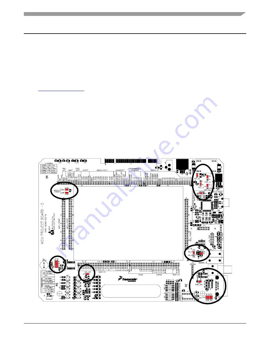
2.
Verify that all the factory default jumper settings are configured properly on the MCU Project
Board – 2 as shown by
Figure 1
. Highlighted blocks indicate the “on” or “installed” position of
jumpers. Circles indicate the location on the project board where the jumpers are located. Table 1
summarizes the default state for the jumper settings. Please refer to MCU Project Board – 2 User
Guide for more details and alternative configurations.
Figure 1. MCU Project Board – 2 Default Jumper Settings


