FR200F series Special Purpose Inverter
- 21 -
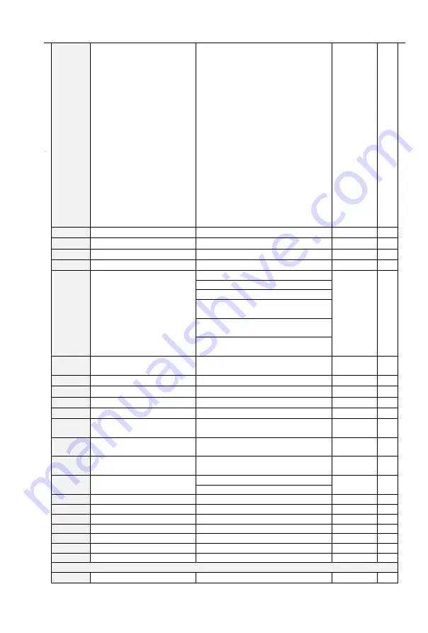
6: Drive in 0Hz running 2(output at
stop)
7: Upper limit frequency attained
8: Lower limit frequency attained
9: Frequency attained
10: Inverter is ready to work
11: Drive (motor) overloaded alarm
12: Inverter overheat warning
13: Current running time attained
14: Accumulative power-on time
attained
15: Consecutive running time
attained
16: PLC cycle completed
17: Set count value attained
18: Designated count value
attained
19: Length attained
20: Under load alarm
21:Brake output
F05.04
Y1 output delay time
0.0
~
6000.0s
0.0s
△
F05.05
Y2 output delay time
0.0
~
6000.0s
0.0s
△
F05.06
R1 output delay time
0.0
~
6000.0s
0.0s
△
F05.07
R2 output delay time
0.0
~
6000.0s
0.0s
△
F05.08
Enabled state of digital
output
Unit's place: Y1
0000
×
0: Positive logic
1: Negative logic
Ten’s place: Y2 (same as unit's
place)
Hundred’s place: Relay 1 output
(same as unit's place)
Thousands place: Relay 2 output
(same as unit's place)
F05.09
Detection width of
frequency attained
0.00
~
20.00Hz
5.00Hz
×
F05.10
FDT1 upper bound
0.00
~
Fmax
30.00Hz
×
F05.11
FDT1 lower bound
0.00
~
Fmax
30.00Hz
×
F05.12
FDT2 upper bound
0.00
~
Fmax
30.00Hz
×
F05.13
FDT2 lower bound
0.00
~
Fmax
30.00Hz
×
F05.14
Consecutive running
time
0.0
~
6000.0Min 0.0:Disabled
0.0Min
×
F05.15
Accumulative power-on
time setting
0
~
65535h 0:Disabled
0h
×
F05.16
Accumulative running
time setting
0
~
65535h 0:Disabled
0h
×
F05.17
Brake control selection
0: Disabled
0
×
1: Enabled
F05.18
Brake opened frequency
Closed frequency ~30.00Hz
2.50Hz
×
F05.19
Brake opened current
0.0~200.0%
0.0%
△
F05.20
Brake open waiting time
0.00~10.00s
0.00s
×
F05.21
Brake open operating time
0.00~10.00s
0.50s
×
F05.22
Brake closed frequency
0.00Hz~opened frequency
2.00Hz
×
F05.23
Brake close waiting time
0.00~10.00s
0.00s
×
F05.24
Brake close operating time
0.00~10.00s
0.00s
×
Group F06 Analog and Pulse Input
F06.00
Minimum input of curve
0.0%
~
input of inflection point1
1.0%
△


