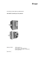


Type V370
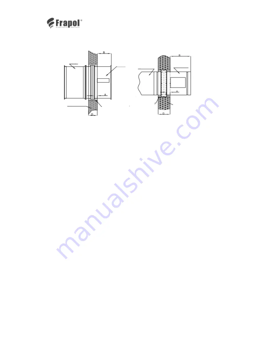
Type RK370
Fig. 6a
Fig. 6b
4.4.1.3.
The gap between the valve casing and the fire barrier must be carefully filled with cement,
lime-cement mix or PROMASTOP MG III fire-protective mortar. It is prohibited to force in any
pieces of brick or concrete while sealing, as this might lead to deformation of the casing
(particularly in cases of valves with large cross-sections), and thus prevent free rotation of the
partition and its closure (friction in slide bearings, or friction between the partition and the
casing).
4.4.2. Valves installed in a light fire barrier made of plaster and cardboard boards acc. to diagram in
Fig. 7a and 7b.
4.4.2.1. Place the valve in the fire barrier opening prepared acc. to section 4.2.2. so that, for barrier
with class EI120 and thickness of 125 mm, the cut-off partition of the valve should remain in
the axis of barrier thickness. Valves of V370 type must protrude from the wall on the drive side
to the distance of 218 mm, while valves of RK370 type must protrude from the wall on the
drive side to the distance of 213 mm. Assembly of valves in this version in fire barriers with
lower fire resistance classes must be made observing valve setting against the barrier acc. to
the data in Table 2.
4.4.2.2. Connect the valves with the suspended ventilation ducts on both sides of the fire barrier.
4.4.2.3. After appropriate valve setting in the fire barrier, seal it with mineral wool with thickness of min.
100 kg/m
3
and cover the wall with plaster boards acc. to Fig. 7a; 7b and 7c.
duct
duct
valve
valve
drive
Fire barrier
Fire barrier
Cement, lime-cement
mortar or promastop MG
III
Cement, lime-cement
mortar or promastop
MG III
Drive board


