of it. Wax or oil the M4 bolt thread, and pass the bolt
thru’ the hole in the ply. Apply a
little
5 minute epoxy
to the edges of the ply plate, and then screw the bolt
up into the T-nut in the fin from inside the fuselage.
Rudder Servo
Any good quality mini-servo of at least 3kg torque is
sufficient for rudder control, and we have fitted a dig-
ital JR3401 here.
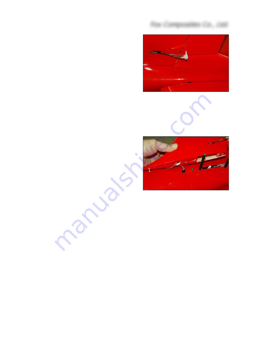
Fit the rudder horn, which is made from the supplied
M3 x 35mm threaded rod and plastic adapter (in a
similar manner to that of the ailerons),
before
mount-
ing the rudder servo. Mark a line 10mm back from
the L.E. of the rudder, and drill the Ø 2.2mm hole
right thru’ on this line about 10 - 12mm up from the
base of the rudder. The hole should be just behind,
or against, the balsa rudder spar, and it should pass
thru’ the small plywood reinforcing plate that is in-
stalled during manufacture. Thread the hole, right
thru' the rudder, using an M3 tap. Drill an access
hole (about Ø 8mm) in the base of the rudder now,
so that you can apply some glue to lock the M3
threaded rod in place later.
Sand both ends of the threaded rod flat, and screw
on the plastic adapter provided. Screw it into the
tapped hole until the other end is flush with the right
side of the rudder. The M3 rod must now be secured
in place, by applying glue through the hole you
drilled in the base of the rudder. Apply one drop of thick CA and, when cured, add some 30 minute
epoxy and micro-balloons mixture.
Mark the linkage line parallel to the root of the rudder (in-line with the airflow), on masking tape.
File a
small
slot in the left side of the fin, on the marked line, so that you can check the correct depth
of the servo mount using the linkage, before gluing the mount into place. The back of the slot
should be about 35mm in front of the T.E. of the fin. The linkage will need to be approx. 85mm long,
clevise pin-to-pin.
Adjust the milled plywood mount to fit your servo, and sand as needed so that it fits snugly inside
the fin. Fit a short servo arm onto the servo, set the travels to 100%, and centre it with your TX so
that the servo arm is at 90° to the case. Slide the mount (and servo) into the fin, and connect it to
the rudder horn with the linkage to set the alignment of the mount exactly. Adjust the length of the
slot now for linkage clearance. The clevise can be on the inner hole fo the servo arm, as the rud-
der travels required are very small (10mm both ways). Tack the mount in place with 2 very small
drops of thick CA, carefully remove the servo, and secure the mount properly with a fillet of 30
minute epoxy and micro-balloons all around.
The servo cable goes upwards and thru’ the slot at the top of the front spar, and then down and
out of the milled hole in the base - in front of the T-nut. You can glue the extension lead socket into
the top of the fuselage for easy connection at the airfield.
Fox Composites Co., Ltd.
20
(above) M2 hardware used for linkage.
Only small throws (10mm both ways) are
needed as rudder is very powerful.
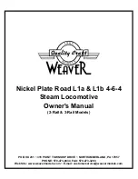
(below) Fin joiners must be permanently
glued into fuselage. M4 bolt into T-nut in
Fin secures it for flight. Note optional Ø
3mm tube at front of fin for alignment.


