glued inside the edges of the retract bay keep them
flush. You can use clear tape, or small screws, to
hold the covers in position as shown.
We have not designed this model to have any gear
doors, but an enterprising modeller could cut out the
retract covers to make operating inner gear doors if
wished, and even outer doors or strut covers. A sim-
ple spring-loaded mechanical linkage could be used,
so that the wheel pulls the inner door closed - with-
out having to use separate servos, pneumatic cylin-
ders, valves or door sequencing units.
The retract tubing, together with the aileron and flap
servo extension cables, can pass up into the fuse-
lage thru’ a hole in the upper surface of the wing near the root, immediately behind the main wing
spar, and then enter the cockpit area thru’ the same hole as the turbine services. Don’t forget to
protect these from the sharp edges of the composite sandwich by installing rubber grommets in
the holes. Make sure to secure all of these vital connections for flight, so they cannot flap around
in the high-speed air that is going into the turbine compressor.
Wing Fences
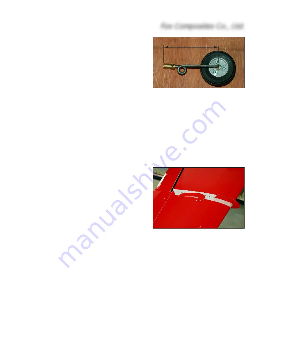
Included in the hardware bag are 2 small fibreglass
wing fences, which can be glued onto the leading
edge of the wings - exactly in line with the joint be-
tween the flaps and ailerons (scale position) if you
wish.
However, we noticed no difference to the flight char-
acteristics with them on, or off, and they are very
easy to break off when you put the wings in the pro-
tection bags for transport or storage !
Fuselage:
The fuselage is a fibreglass and epoxy moulding, without a foam sandwich, painted single-colour
in the moulds. We recommend that you lightly sand the
complete
inside surface of the fuselage
now, with 120 - 240 grit sandpaper - and this is especially important in the nose area as access is
more difficult after the nosegear is fitted and you may want to fit supports for batteries etc in there
later. This operation will also remove any loose glass strands that might get in your hands later.
Generally you can follow the assembly sequence shown below for simplest access, and we like
to work from the back of the fuselage forwards to the nose and install the gear and extension leads
etc as we progress. If installing one of the turbines recommended, or one of similar weight, and a
Fox Composites Co., Ltd.
14
(above) The milled fibreglass wing fences
supplied in the kit can be glued on to the
top surface in line with Aileron/Flap joint.
97mm
2.75” wheel
(above) For the Spring-Air 300/700 units
and 2.75” wheels the leg length is 97mm
from the end of the brass adapter (or
wire leg) to the centre of the axle.


