background image


Model 914-HDE User Manual 

Focal Technologies Corporation 

A Moog Inc. Company 

Document Number: 914-0601-00 Rev. 4.0


LIST


OF


TABLES 
 

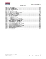
Table 1: 914-HDE Versions ....................................................................................................................... 3-4


Table 2: Power Connector Pinout .............................................................................................................. 3-5


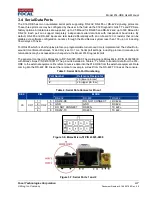
Table 3: Serial Data Port Numbering ......................................................................................................... 3-7


Table 4: Serial Data Connector Pinout ...................................................................................................... 3-7


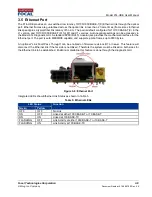
Table 5: Ethernet LEDs .............................................................................................................................. 3-8


Table 6: 914-HDE Diagnostic LEDs ........................................................................................................... 3-9


Table 7: 914-HDE Diagnostic LED Header Pinout .................................................................................. 3-10


Table 8: Sample Flux Budget Calculation ................................................................................................ 3-11


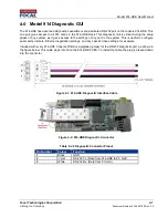
Table 9: J8 Diagnostic Connector Pinout ................................................................................................... 4-1


Table 10: Serial Data Port Numbering ....................................................................................................... 5-2


Table 11: Serial Data Connector Pinout .................................................................................................... 5-2


Table 12: Power Connector Pinout ............................................................................................................ 5-2


Table 13: 914-HDE Diagnostic LEDs ......................................................................................................... 5-3


Table 14: 914-HDE Diagnostic LED Header Pinout .................................................................................. 5-4


Table 15: 914-VDX Expansion Channel Configuration .............................................................................. 5-5


Table 16: Signal Types and Required Bandwidths .................................................................................... 6-1


Table 17: Available Bandwidth by Card Version ........................................................................................ 6-1


Table 18: Example 914-HDE L1 System Requirements ............................................................................ 6-1


Table 19: Example 914-HDE L1 System Solution ..................................................................................... 6-1


Table 20: Example 914-HDE M1 System Requirements ........................................................................... 6-2


Table 21: Example 914-HDE M1 System Solution .................................................................................... 6-2


Table 22: Example 914-HDE H1 System Requirements ........................................................................... 6-2


Table 23: Example 914-HDE H1 System Solution .................................................................................... 6-2


Table 24: Electrical Specification ............................................................................................................... 7-3


Table 25: Environmental Specification ....................................................................................................... 7-3


Table 26: Firmware Revisions.................................................................................................................... 8-2


Содержание 914-HDE

Страница 1: ...Y CONTRACT OR BY OPERATION OF LAW NO PORTION OF THIS DATA DRAWING DOCUMENT SHALL BE REPRODUCED OR DISCLOSED OR COPIED OR FURNISHED IN WHOLE OR IN PART TO OTHERS OR USED BY OTHERS FOR ANY PURPOSE WHATS...

Страница 2: ...imum 350Mb s Ethernet throughput in M1 mode while 3G SDI is plugged 3G SDI Level B support Update to colour coded diagnostic cable EM 2016 06 27 Rev 3 0 Added sections 7 0 Firmware Updates 8 0 Feature...

Страница 3: ...uration 4 7 4 1 3 914 HDE Ethernet Port Configuration 4 7 Expansion Cards 5 1 5 1 914 VDX 5 1 5 1 1 914 VDX Serial Data Ports 5 2 5 1 2 914 VDX Composite Video Channels 5 1 5 1 3 914 VDX Power 5 2 5 1...

Страница 4: ...v A Moog Inc Company Document Number 914 0601 00 Rev 4 0 7 5 914 HDE Product Handling 7 4 7 6 Accessories 7 4 Firmware Updates 8 1 8 1 Firmware Compatibility 8 2 Feature Upgrades 9 1 Troubleshooting 1...

Страница 5: ...Serial Data Connector Pinout 5 2 Table 12 Power Connector Pinout 5 2 Table 13 914 HDE Diagnostic LEDs 5 3 Table 14 914 HDE Diagnostic LED Header Pinout 5 4 Table 15 914 VDX Expansion Channel Configur...

Страница 6: ...2 Figure 4 4 914 HDE Card Info 4 3 Figure 4 5 914 HDE Voltage and Junction Temperature Information 4 4 Figure 4 6 914 HDE Optical Link Status 4 5 Figure 4 7 914 HDE Signal Status 4 6 Figure 4 8 914 HD...

Страница 7: ...igabit Ethernet Gbps Gigabits Per Second HD High Definition HS High Speed HDE HD Video Serial Data Ethernet I O Input output kbps Kilobits Per Second LC PC Lucent Connector Physical Contact LED Light...

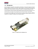
Страница 8: ...s been optimized for low power operation and delivery of low latency uncompressed 3G HD SD SDI video A series of expansion cards are available allowing additional composite video channels serial data...

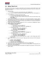
Страница 9: ...with 5 V to 12 V power Refer to Section 3 2 Verify all system voltages in the 914 Diagnostic GUI 6 Configure all cards via Diagnostic GUI a Configure console HDE i Serial protocol Refer to Section 4 1...

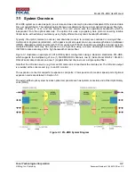
Страница 10: ...division multiplexer WDM Standard systems operate with 1310 nm uplink and 1550 nm downlink wavelengths In larger systems multiple 914 HDE units may be combined on a single fiber using a coarse wavele...

Страница 11: ...en them is the EEPROM configuration and optical transceiver The 914 HDE does not use physical DIP switches for system configuration and settings All settings are accessed via the Model 914 Diagnostic...

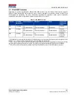
Страница 12: ...nels Ethernet Video Supported Expansion Cards L1 1 75 Gb s 2x RS 232 485 422 1x 10 100 1000 Mb s 1x HD SD SDI 914 DX M1 3 5 Gb s 2x RS 232 485 422 1x 10 100 1000 Mb s 1x 3G HD SD SDI 914 DX 914 VDX 91...

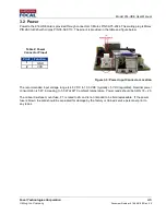
Страница 13: ...ow Figure 3 3 Power Input Connector Location The recommended input voltage range is 4 5 VDC to 13 0 VDC typically 5 VDC regulated Nominal power consumption is 5 W increasing to 5 5 W at 60o C ambient...

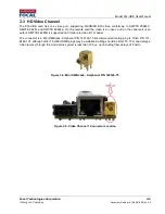
Страница 14: ...n input and on the console it is an output SMPTE 424M B is supported on firmware revision B1 or newer The connector is a Mini SMB jack Amphenol P N 142146 75 Recommended mating plug is Cinch P N 131 8...

Страница 15: ...able turn around time is implemented The default turn around time timeout between Tx and Rx is set to 1 ms Serial port settings including protocol timeouts and terminations may be accessed and changed...

Страница 16: ...45 modular jack provides the mechanical interface for the Ethernet port The port is auto MDI MDIX capable and supports jumbo frames up to 9000 bytes An optional Link Fault Pass Through can be enabled...

Страница 17: ...s LED is lit the card is not powered properly and will not function D6 Green Indicates that the card is powered properly when lit D7 Green Indicates a valid video signal is present when lit D8 Green I...

Страница 18: ...st 0 050 1 27mm spacing ribbon cables Table 7 914 HDE Diagnostic LED Header Pinout Pin Name Description 1 3 3V 3 3V This pin can be used to drive the LEDs Maximum current is 0 5A 2 LINK Indicates a va...

Страница 19: ...ber link and a FORJ Actual losses can vary widely from this each system flux budget calculation must use data based on actual parts in use Table 8 Sample Flux Budget Calculation Component Uplink 1310...

Страница 20: ...rt in the system This is useful to configure serial port protocols Ethernet negotiation settings and any special video settings for example Included with every 914 HDE Console PCBA is a pigtailed jump...

Страница 21: ...a serial COM port connected to the 914 HDE diagnostic port Microsoft NET version 4 0 or greater must be installed on the host computer Installation of the Model 914 diagnostic GUI will involve copying...

Страница 22: ...a green heart will be seen at the top left of the screen near the COM port listing If the heart appears red the link has not been established Verify the COM port number and the wiring harness to the P...

Страница 23: ...d expansion buttons allows more system information to be extracted Figure 4 5 shows all the system voltages as well as the FPGA junction temperature A green background indicates that the observed stat...

Страница 24: ...Moog Inc Company Document Number 914 0601 00 Rev 4 0 Figure 4 6 shows the optical link status including information provided by the optical transceiver such as transmit and receive optical power and...

Страница 25: ...4 6 A Moog Inc Company Document Number 914 0601 00 Rev 4 0 Figure 4 7 shows the current status of each input output signal video serial and Ethernet Receive serial activity is shown in yellow to match...

Страница 26: ...s These settings are non volatile and do not need to be re configured each time the 914 HDE is powered Figure 4 8 914 HDE Serial Port Configuration 4 1 3 914 HDE Ethernet Port Configuration Figure 4 9...

Страница 27: ...nels and 2 low speed channels available The expansion connector provides for 16 15 mm spacing between cards when directly stacked together For tight spaces and or larger stacks Focal Technologies can...

Страница 28: ...round time is implemented The default turn around time timeout between Tx and Rx is set to 1 ms Serial port settings including protocol timeouts and terminations may be accessed and changed via the Mo...

Страница 29: ...the Diagnostic GUI Latency through the Mux Demux system is less than 500 s not including fiber delays of 5 ns m Coaxial shielding on the connectors is directly tied to ground care must be taken to en...

Страница 30: ...P N 09 75 2024 The mating plug is Molex P N 26 03 4020 with crimps P N 08 52 0113 The pinout is provided in the table and figure below Figure 5 6 Power Input Connector Location The recommended input...

Страница 31: ...outside of the supported range of 4 5 to 13 5 V Recommended input voltage is 5 VDC When this LED is lit the card is not powered properly and will not function D8 Green Indicates that the card is powe...

Страница 32: ...used with most 0 050 1 27mm spacing ribbon cables Table 14 914 HDE Diagnostic LED Header Pinout Pin Name Description 1 3 3V 3 3V This pin can be used to drive the LEDs Maximum current is 0 5A 2 VIDEO...

Страница 33: ...1 configures which expansion channel each card uses The card closest to the 914 HDE must be configured for expansion channel 1 with each subsequent card configured for the next channel is succession N...

Страница 34: ...ole 914 HDE to the 914 Diagnostic GUI via a local COM port Ensure a stable optical link is present and the cards are stacked together in the correct order with the correct expansion settings as per th...

Страница 35: ...v 4 0 5 1 8 914 VDX Serial Port Configuration To alter the serial port settings from the GUI click on the Serial Info then Config tab as shown in Figure 5 12 Select new settings on a port by port basi...

Страница 36: ...14 VDX Diagnostics In a similar manner to the 914 HDE the 914 VDX has available diagnostics from the GUI including all voltages and the junction temperature of the FPGA Any value shown in green is ope...

Страница 37: ...odel 914 Diagnostic GUI This expansion card requires 2 medium speed expansion channels 5 3 914 DX Preliminary Information The 914 DX provides 6 channels of isolated serial data The serial channels are...

Страница 38: ...914 HDE Serial channels Diagnostics and Low Speed expansion channels 100 Mb s Always Enabled 10 Mb s Ethernet 10 Mb s 100 Mb s Ethernet 100 Mb s 1000 Mb s Ethernet 1000 Mb s SD SDI 300 Mb s HD SDI 155...

Страница 39: ...HDE M1 1 1x HD SDI 2x Serial 1x Gigabit Ethernet 914 DX 2 12x Serial Channels 6 per card 914 VDX 1 2x Analog Video 4x Serial 914 EX 1 2x Fast Ethernet Channels 6 3 Example 914 HDE H1 System Table 22 E...

Страница 40: ...tacks Stacking height for expansion cards is 16 00 mm to 17 22 mm Nominal height should be 16 15 mm 0 636 to take into account component tolerances A 4 00 mm minimum standoff should be used under the...

Страница 41: ...essive fiber bends It is good practice to carefully clean all fiber connections prior to mating them for testing or installation If the basic optical link is present LED D8 is on there should be data...

Страница 42: ...e by using thermal management to ensure electronic parts do not exceed a case temperature of 85C Input amperage must not exceed 4 A if close to 20 W is required the power supply must use a higher nomi...

Страница 43: ...ed minimum fiber bend radius even momentarily Mishandling may cause damage to the optical transceiver video or serial connectors or internal components The multiplexers must always be handled appropri...

Страница 44: ...the firmware bin file to the same computer 4 Connect the diagnostic port on the card to be updated to a COM port on the computer as per section 3 of this manual a J8 on the 914 HDE b J7 on the 914 VDX...

Страница 45: ...rows Each row is only compatible with other products and revisions in that row Contact Focal Technologies regarding non standard updates of older products or for compatible expansion cards for 914 HDE...

Страница 46: ...and Feature Code Both codes are 16 digit hexadecimal alpha numeric numbers 2 Open the 914 HDE diagnostic GUI with the Console 914 HDE connected to a local COM port as per manual section 3 3 Use the To...

Страница 47: ...ee in the 914 Diagnostic GUI is not showing up a Press Stop and then Start at the bottom of the GUI to refresh the displayed cards b Verify that the cards have compatible firmware versions per Section...

Страница 48: ...ed i Check connection status in GUI are both ends linked at the same speed If not force the links to be the same speed ii Is the GUI reporting dropped frames If so too much bandwidth is required by yo...

Страница 49: ...applied 9 914 VDX Expansion channel shows faults a Alter the differential voltage in the 914 VDX configuration settings tab in the GUI Reduce the voltage for short expansion links increase for longer...

Отзывы: