Model 914-HDE User Manual
Focal Technologies Corporation
5-3
A Moog Inc. Company
Document Number: 914-0601-00 Rev. 4.0
5.1.4 914-VDX Diagnostic LEDs
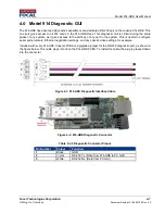
The 914-VDX card includes 15 on-board diagnostic LEDs. A description and location of each LED is provided
in Table 6 and Figure 3-9.
Table 13: 914-HDE Diagnostic LEDs
Reference
Designator
Color
Description
D1
Green
Flashing LED indicates serial channel 3 is transmitting to external equipment.
D2
Yellow Flashing LED indicates serial channel 3 is receiving from external equipment.
D3
Green
Flashing LED indicates serial channel 4 is transmitting to external equipment.
D4
Yellow Flashing LED indicates serial channel 4 is receiving from external equipment.
D7
Red
Indicates a power fault when lit. A power fault is encountered when the input voltage
falls outside of the supported range of 4.5 to 13.5 V. Recommended input voltage is
5 VDC. When this LED is lit, the card is not powered properly and will not function.
D8
Green
Indicates that the card is powered properly when lit.
D9
Green
Indicates the 914-VDX is configured for Console mode.
D10
Green
Indicates a valid video signal is present on channel 1 when lit
D11
Green
Indicates a valid video signal is present on channel 2 when lit
D12
Green
Indicates a valid expansion link is being received. (data frames are present)
D13
Red
Indicates the expansion link is in fault condition. (little or no valid data is present)
D14
Green
Flashing LED indicates serial channel 1 is transmitting to external equipment.
D15
Yellow Flashing LED indicates serial channel 1 is receiving from external equipment.
D16
Green
Flashing LED indicates serial channel 2 is transmitting to external equipment.
D17
Yellow Flashing LED indicates serial channel 2 is receiving from external equipment.
Figure 5-7: VDX Diagnostic LEDs


