


1.2–6.6 kV drive units
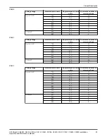
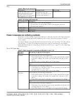
Table 11: Stator temperature monitoring configuration, 1.2–6.6 kV
Standard /
Optional
Monitoring Configuration Description
Standard
This configuration uses the following:
• Three thermistors, connected in series, are incorporated in the coil ends of the
stator windings. T
Ref
=155°C (310°F) for medium-voltage drive units.
• Three Pt100 sensors, one for each phase, are incorporated in the windings.
There are three additional thermistors, and 3 additional Pt100 sensors, already in
place in the stator windings as reserves. See below for sensor markings.
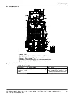
Stators used in the 1.2–6.6 kV drive units are equipped with 3 Pt100 sensors marked 19:20, 21:22, and
23:24. These are connected at the plinth on the terminal plate. The stator is also equipped with a duplicate
set of 3 Pt100 sensors, marked 19s:20s, 21s:22s, and 23s:24s. This duplicate set is not connected to the
terminal plate as long as the first set of 3 Pt100 sensors are functioning; it is kept in reserve as a back-up
set. The ends of the reserve sensor leads are isolated, and leads bundled among the other cables, until the
back-up Pt100 sensors are needed.
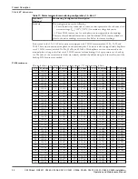
Pt100 resistance
This table shows the relationship between temperature (°C) and resistance (ohms).
T, °C R, ohms
T, °C R, ohms
T, °C R, ohms
T, °C R, ohms
T, °C R, ohms
0
100.00
33
112.83
66
125.54
99
138.12
132
150.57
1
100.39
34
113.22
67
125.92
100
138.50
133
150.95
2
100.78
35
113.61
68
126.31
101
138.88
134
151.33
3
101.17
36
113.99
69
126.69
102
139.26
135
151.70
4
101.56
37
114.38
70
127.07
103
139.64
136
152.08
5
101.95
38
114.77
71
127.45
104
140.02
137
152.45
6
102.34
39
115.15
72
127.84
105
140.39
138
152.83
7
102.73
40
115.54
73
128.22
106
140.77
139
153.20
8
103.12
41
115.93
74
128.60
107
141.15
140
153.58
9
103.51
42
116.31
75
128.98
108
141.53
141
153.95
10
103.90
43
116.70
76
129.37
109
141.91
142
154.32
11
104.29
44
117.08
77
129.75
110
142.29
143
154.70
12
104.68
45
117.47
78
130.13
111
142.66
144
155.07
13
105.07
46
117.85
79
130.51
112
143.04
145
155.45
14
105.46
47
118.24
80
130.89
113
143.42
146
155.82
15
105.85
48
118.62
81
131.27
114
143.80
147
156.19
16
106.24
49
119.01
82
131.66
115
144.17
148
156.57
17
106.63
50
119.40
83
132.04
116
144.55
149
156.94
18
107.02
51
119.78
84
132.42
117
144.93
150
157.31
19
107.40
52
120.16
85
132.80
118
145.31
151
157.69
20
107.79
53
120.55
86
133.18
119
145.68
152
158.06
21
108.18
54
120.93
87
133.56
120
146.06
153
158.43
22
108.57
55
121.32
88
133.94
121
146.44
154
158.81
23
108.96
56
121.70
89
134.32
122
146.81
155
159.18
24
109.35
57
122.09
90
134.70
123
147.19
156
159.55
25
109.73
58
122.47
91
135.08
124
147.57
157
159.93
26
110.12
59
122.86
92
135.46
125
147.94
158
160.30
27
110.51
60
123.24
93
135.84
126
148.32
159
160.67
28
110.90
61
123.62
94
136.22
127
148.70
160
161.04
29
111.28
62
124.01
95
136.60
128
149.07
30
111.67
63
124.39
96
136.98
129
149.45
31
111.94
64
124.77
97
137.36
130
149.82
32
112.45
65
125.16
98
137.74
131
150.20
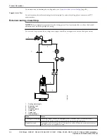
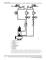
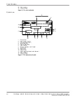
Product Description
32
C3300/6x5, C/R3231, C3240, C3306, C3312, C3351, C3356, C3400, C3501, C3531, C3602, C3800 Installation,
Operation and Maintenance Manual
Содержание C/R3231
Страница 2: ...End of Disclaimer text ...
Страница 4: ......
Страница 170: ......
Страница 171: ......


