Logix
®
420 Digital Positioner FCD LGENIM0106-07-AQ – 10/15
22
10.3 Menu Features
10.3.1 Status
►
Status
►
Command (mA)
► C
ommand (%)
►
Position (%)
► T
emperature
►
Valve Cycles
►
Valve Travel (%)
The Status menu is used to view information about the configuration
and operation of the system.
Command
displays the final command in mA.
Command
displays the final command in %.
Position
displays the valve position in %.
Temperature
displays the temperature inside the positioner.
Valve Cycles
are counted each time the positioner changes direction.
The movement must be beyond a dead-band window. This window is
set to 0.5% as a default, but can be changed using the DTM.
Valve Travel
is counted in small increments every time the valve moves
beyond the dead-band window. The travel is displayed in % of full
stroke.
10.3.2 Alerts and Alarms
►
Alerts and Alarms
►
Current Alarms (Prioritized)
►
Event History
►
Last Event
►
2nd Event
►
3rd Event
*
*
*
►
32nd Event
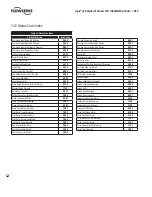
The Alerts and Alarms menu shows current and past alarms, warnings,
alerts, and calibrations.
Current Alarms
displays all events that are actively sounding.
Event History
displays past 32 events including alarms, warnings,
alerts, and calibrations. The event that occurred most recently is
displayed first (event 32) with later events recorded below.
10.2.3 Partial Stroke Test
►
Partial Stroke Test
►
Start
►
Last Result
The Partial Stroke Test (PST) menu provides the user the ability to start
a PST and see the results of the latest PST.
1
CAUTION: Performing a Partial Stroke Test will result in valve
movement and the inability to operate the valve until the test
is complete. Notify proper personnel that the valve may stroke,
and make sure the valve is properly isolated if required by plant
procedures.
Start
allows the user to initialize the (PST).
Last Result
shows “Pass” or “Fail” from the last PST attempt.
10.3.4 Calibration
►
Calibration
►
Stroke/Quick Calibration
►
Command Input Calibration
►
Calibration Dates
The Calibration menu allows the user to calibrate the positioner’s
sensors. The positioner can accurately control with only a Quick-Cal.
Typically this is all that is needed. A friction calibration is recommended
if the positioner has been upgraded to Pro diagnostics. See section 8
STARTUP for more details.
1
CAUTION: Performing a calibration may result in valve movement
and the inability to operate the valve until the calibration is
complete. Notify proper personnel that the valve may stroke, and
make sure the valve is properly isolated before proceeding.
Stroke/Quick Calibration
starts an automatic calibration of the position
feedback sensor. The stroke calibration determines the closed (0%)
and open (100%) positions of the valve and gathers information
about the response of the valve (such as valve stroke time) in order to
determine the gains. The gains are then set automatically. After a stroke
calibration, the positioner is ready to control. See section 8.4 STROKE
CALIBRATION for more information.
Command Input Calibration
is used to adjust the input range. Set the
lowest current (Set 0%) and the highest current (Set 100%) that will be
used. The default input range is 4 to 20 mA. The “Set 0%” value must
be lower than the “Set 100% value.


