background image

User Manual X8400 sc 


2.3  Key features of the X8400sc camera 


1.3 million pixels – 1280x1024 

The  X8400sc  provides  1.3  million  pixels  per  image,  allowing  enlarging  the  area  under 
inspection  with  same  instantaneous  field  of  view  (IFOV)  lenses  or  increasing  the  spatial 
resolution with the same field of view (FOV). The snapshot integration ensures that all pixels 
are temporally coherent. 


Fast Frame Rate 

The FLIR X8400sc Series have an adjustable frame rate of up to 106 Hz full frame and more 
than 3 kHz at 48x4. Windowing allows a subset of the total image to be selectively read out 
with user adjustable window size. The sub-sample windows can be arbitrarily chosen and are 
easily defined. 


14-Bit Digital Image Data 

The  X8400sc  camera  detector  is  digital.  The  A/D  conversion  is  performed  directly  into  the 
ROIC in 14-bit depth. The embedded digitalization improves noise and linearity performances 
to an outstanding standard. 


Outstanding measurement accuracy 

High  accuracy  of  +/-  1ºC  or  +/-  1%  produces  sensitive  thermal  images.  The  FLIR  X8400sc 
can  measure  temperatures  up  to  +3,000º  C.  The  FLIR  X8400sc  detects  temperature 
differences smaller than 25mK (18mK typically).  


CNUC™ Calibration 

CNUC™  is  a  proprietary  calibration  process  that  provides  beautiful  imagery  and 
measurement  stability.  CNUC™  allows  for  flexible  integration  time  adjustments  without  the 
need  to  perform  non-uniformity  corrections.  CNUC™  calibration  also  produces  accurate 
measurement stability regardless of camera exposure to ambient temperature variations. 


Hypercal™ 

Hypercal™ ensures the best measurement range with the highest sensitivity. Simply set the 
desired  lower  and  upper  temperature  limits  and  the  camera  will  automatically  adjust  to  the 
appropriate integration (exposure) time. 


Auto exposure 


The camera automatically adjusts its temperature range to best fit the thermal scene. 


Presets 

Up  to  eight  presets  and  their  associated  parameters,  such  as  integration  time,  frame  rate, 
window size and window location, are available for instant selection with a single command. 
These  presets  can  be  used  in  Dynamic  Range  Extension  (DRX)  mode  (also  called 
Superframing”)  which  allows  the  acquisition  of  thermal  data  from  up  to  four  user-defined 
temperature  ranges  simultaneously,  then  merges  those  streams  into  a  single  real-time  data 
stream that spans all four temperature ranges, effectively  extending  dynamic range from 14 
bit to 16 bit. 


Multiple Triggering Modes and Synchronizing Interfaces 

The  X8400sc  camera  provides  different  interfaces  to  support  maximum  flexibility  for 
synchronizing the camera to external events, as well as synchronizing external events to the 
camera. 

o


Sync In (TTL) 

o


Sync Out 

o


Trigger In 


Multiple Video Outputs 


The X8400sc camera features multiple independent and simultaneous videos: 

o


Digital 14-bit video – CameraLink® Base or Medium  

o


Digital 14-bit video – Gigabit Ethernet – GigEVision Compliant 

o


Digital 8-bit Video – DVI format 1080p30 digital output 


Wide range of interchangeable lenses  

The  FLIR  X8400sc  comes  with  an  advanced  high  performance  optical  design  with  lens 
recognition  and  automatic  measurement  adjustments.  It  is  also  possible  to  manually  adjust 
the focus directly on the camera. A temperature probe is integrated in the lens for improved 
measurement accuracy and drift compensation. 


A wide range of lenses and various extension rings are available. 


Motorized filter wheel 

The  FLIR  X8400sc  contains  a  4  slot  motorized  filter  wheel  with  automatic  filter  recognition 
and measurement parameter adjustment. The removable filter holders contain an integrated 
temperature probe for improved measurement accuracy. 

Содержание X8400sc

Страница 1: ...User Manual X8400 sc 1 X8400sc User Manual Document Number DC085U Version C Issue Date 08 03 2013...

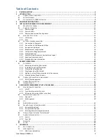
Страница 2: ...5 1 1 Removing an optical filter holder 23 5 1 2 Installing an optical filter holder 23 5 1 3 Filter holder identification 24 5 1 4 Creating custom filter holder 24 5 1 5 Adding a custom filter parame...

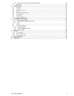
Страница 3: ...ECTOR FPA 51 8 7 CAMERA LINK 51 8 8 EXTENSION CONNECTOR 51 9 MAINTENANCE AND SERVICE 52 9 1 CAMERA AND LENS CLEANING 52 9 1 1 Camera Body Cables and Accessories 52 9 1 2 Lens 52 9 2 COOLER 52 9 3 FLIR...

Страница 4: ...User Manual X8400 sc 4 1 REVISION HISTORY Version Date Author Changes A 14 05 2012 E VANNEAU Creation B 19 12 2012 E VANNEAU Modification for new version C 19 02 2013 E VANNEAU Modification for V2013...

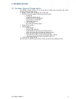
Страница 5: ...licable o Camera files on a CD ROM o Optical cleaning tissue o Filter holding tool o Micro SD card with SD adapter Camera Power supply Camera cables o Power Supply o Ethernet GigE with locks o 50 Ohms...

Страница 6: ...Indium Antimonide InSb detector to cover the 1 5 5 5 m Midwave infrared band The X8400sc is a stand alone imaging camera that interfaces to host PCs using standard interfaces including Gigabit Etherne...

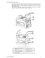
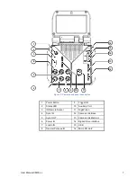
Страница 7: ...9 Trigger IN 2 Status LED 10 Auxilliary Port 3 IR Remote Sensor 11 GigEVision 4 Sync IN 12 Camera Link Base 5 Sync OUT 13 Camera Link Medium 6 Power IN 14 Digital Video Interface 7 Lockin IN 15 USB 8...

Страница 8: ...he appropriate integration exposure time Auto exposure The camera automatically adjusts its temperature range to best fit the thermal scene Presets Up to eight presets and their associated parameters...

Страница 9: ...a a smart phone iPhone or a tablet PC iPad Video Color Palettes The X8400sc camera supports a selection of standard and user defined color palettes or grayscale for the DVI video Configuration managem...

Страница 10: ...g oOperating the camera outside of the specified input voltage range or the specified operating temperature range can cause permanent damage oDo not image extremely high intensity radiation sources su...

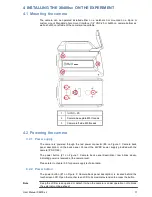
Страница 11: ...he red power connector 6 on Figure 1 Camera back panel description on the back panel Connect the 24VDC power supply provided with the camera PN X1159 The power button 1 on Figure 1 Camera back panel d...

Страница 12: ...s The camera is ready to use when the all status LEDs on back panel are green 2 on Figure 2 Camera back panel description 4 3 Adjusting Field of view Once the camera is installed and running the field...

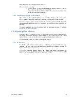
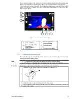
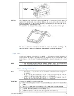
Страница 13: ...ion information 5 Auto exposure 3 Synchronisation information 6 Change Color palette Detaching the touchscreen LCD 4 3 1 1 The LCD screen can be detached from the camera and used remotely when the cam...

Страница 14: ...is used by the camera to compensate for thermal drifts Note FLIR is continuously extending the range of available optics Contact your FLIR sales representative for more information on the newly availa...

Страница 15: ...n you install the lens If this happens clean the lens accordingly to the instructions in section 9 1 2 on page 52 Camera focus can be done manually by rotating the focus ring on the lens Procedure For...

Страница 16: ...Connect the cables to connector 12 and 13 on Figure 2 Camera back panel description This configuration allows reaching the maximum frame frequency of the camera The CameraLink mode is selected with t...

Страница 17: ...n 2 Select the X8400sc camera The camera s IP address is displayed when connected with GigE connection The CameraLink port is displayed when connected with CameraLink 3 Click Connect button to activat...

Страница 18: ...ting modes ITR IWR Each configuration is described with minimum and maximum calibrated temperatures filter and lens configuration Only the configurations which are relevant to the actual camera setup...

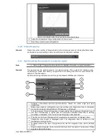
Страница 19: ...The range is shadowed in red and will be applied to the camera after clicking on the Apply Configuration button 3 Activate the range by checking the box If more than one range is activated the camera...

Страница 20: ...rs are set through the ResearchIR Max user interface 1 Activate Deactivate external synchronization Select the active edge and input impedance 2 Based upon camera configuration such as window size int...

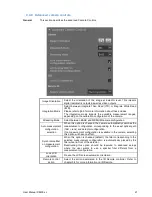
Страница 21: ...option is checked the camera automatically searches the measurement configuration corresponding to the exact optical path filter lens and detector configuration If no measurement configuration is avai...

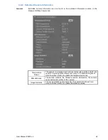
Страница 22: ...with various temperature probes which are used for improving measurement accuracy or for camera diagnostic Click the refresh button to update the temperature values Miscellaneous The section contains...

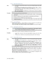
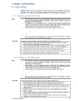
Страница 23: ...he corresponding holes 4 Rotate the filter holder counter clockwise to release the holder from the wheel 5 Gently remove the holder from the camera and store it on its case 5 1 2 Installing an optical...

Страница 24: ...e for more information on blank filter holders Procedure Follow the procedure to assemble a filter within a filter holder 1 Select a holder identifier within the range 40 to 58 This will be the one us...

Страница 25: ...older defined with ID 42 in which the F3221 filter is mounted the following shall be added to the slot ini file Holder 42 F1 F3221 For a holder defined with ID 45 in which the filters F3221 and F1518...

Страница 26: ...ng convention but it can be freely modified XX_YYYY_ZZZZ_WW XX Type of filter NA Narrow LP Low Pass HP High Pass BP Band pass YYYY Cut on in nm ZZZZ Cut off in nm WW Average Transmission application m...

Страница 27: ...nection This application enables to start and stop the image recording on ResearchIR Max Procedure 1 Connect your device smartphone or computer to your camera 2 On a web browser go to http 169 254 242...

Страница 28: ...ol using the NIKON protocol The actions available are the following Start Acquisition on ResearchIR Max Trigger 1 point NUC calibration Trigger Auto exposure Trigger Autofocus Procedure Follow the pro...

Страница 29: ...be determined and corrected There are two types of processes which are used to create the NUC table One Point and Two Points 6 1 1 CNUC General CNUC is a proprietary calibration process A camera calib...

Страница 30: ...n easy task Note 1 C or 1 accuracy is standard for X8400sc camera unless explicitly specified Typically calibration on custom spectral filters or custom optical configurations can show higher accuracy...

Страница 31: ...pixel as bad if RMS noise 8 5 With the absolute threshold the system considers a pixel as bad if its value is higher than this threshold 6 5 Frame Rate and Integration modes General Frame rate is the...

Страница 32: ...35 261 294 330 330 330 330 330 224 219 239 262 290 326 364 364 364 364 364 192 249 270 296 327 365 407 407 407 407 407 160 287 311 339 373 415 460 460 460 460 460 128 339 366 398 435 481 530 530 530 5...

Страница 33: ...330 330 330 330 330 330 330 330 330 330 224 364 364 364 364 364 364 364 364 364 364 192 407 407 407 407 407 407 407 407 407 407 160 460 460 460 460 460 460 460 460 460 460 128 530 530 530 530 530 530...

Страница 34: ...0 270 270 270 320 176 193 215 243 278 319 319 319 319 319 256 216 238 265 298 341 391 391 391 391 391 224 245 269 299 337 385 440 440 440 440 440 192 282 310 344 386 441 503 503 503 503 503 160 332 36...

Страница 35: ...85 885 885 885 885 885 885 885 885 64 1185 1185 1185 1185 1185 1185 1185 1185 1185 1185 56 1294 1294 1294 1294 1294 1294 1294 1294 1294 1294 48 1426 1426 1426 1426 1426 1426 1426 1426 1426 1426 40 158...

Страница 36: ...ge data The generation of a frame consists in two phases integration and data readout Depending on the timing between these two events you can have two basic integration modes Integration Then Read IT...

Страница 37: ...V Low state maximum voltage 0 5 V Polarity User Selectable Max frequency Hz Maximum Frame Rate of the camera for a given detector configuration Minimum Pulse width ns 300 Impedance User selectable 50...

Страница 38: ...with the Sync IN or with the frame rate if the Sync In is not selected It can be used to synchronize other events with the camera It is a TTL signal The Sync OUT setup is described in 4 4 7 Character...

Страница 39: ...ecording time is requested When only few frames are needed to be recorded When NOT to use this configuration When it is needed to trigger each acquisition In that situation it is preferable to use the...

Страница 40: ...the signal is digitalized during the integration of the infrared image and embedded within it It is then recorded by ResearchIR Max and stored in the sequence file image headers Files recorded with R...

Страница 41: ...hoc WLAN network This connection enables to control the acquisition in ResearchIR Max from the camera same action as on LCD screen At the time of writing this manual no image streaming is available on...

Страница 42: ...User Manual X8400 sc 42 4 Connect to http 192 168 64 1...

Страница 43: ...river Installation First Time installation 7 2 1 1 When the camera is connected with USB for the first time Windows detects the camera and prompts to select the driver Procedure Follow the procedure t...

Страница 44: ...r Manual X8400 sc 44 6 Select Browse my computer for driver Software 7 Select Let me pick from a list of device on my computer 8 Select Have Disk 9 Browse and select the file X8400sc X6500sc USB inf f...

Страница 45: ...r software anyway The driver is now installing If it doesn t seem to progress correctly try to unplug the USB cable from the PC 12 Restart the computer 13 The Device manager now shows the new device F...

Страница 46: ...s and select Internet Protocol V4 Click on Properties 3 Set the IP address to 169 254 242 10 with a subnet mask at 255 255 255 0 Click OK 4 The camera can now be accessed With the Windows Explorer to...

Страница 47: ...onnected type the address of the camera in Window Explorer Address can be in the form of The camera IP address 169 254 242 23 The camera SMB name Platinum Procedure Windows Seven default configuration...

Страница 48: ...User Manual X8400 sc 48 7 3 Mechanical General Below are the mechanical interfaces...

Страница 49: ...User Manual X8400 sc 49...

Страница 50: ...enerator Waveform Sinus Triangle Square TTL 0 5 V Frequency range 0 001 Hz 250 kHz Optical Interface Integrated bayonet mount Thermal Interface Internal heat is conductively transferred through the bo...

Страница 51: ...OIC Digital Integration Mode Snapshot Format HxV 1280x1024 Operability 99 5 Charge Handling Capacity 5 8 Me Detector Pitch 15 microns square Maximum Frame Rate Up to 106 Hz full frame Up to 3170 Hz in...

Страница 52: ...change the lens tissue and repeat the operation 4 If dust persists apply propanol 2 RECTAPUR 20 ref PROLABO 839 322 to your lens tissue Use slow even light pressure working from edge to edge across t...

Страница 53: ...pport The FLIR Customer Support Center portal will help you as a FLIR customer to get the most out of your FLIR products The portal gives you access to our support team software and documentation serv...

Страница 54: ...take whatever measures may be required to correct the interference 10 2 For Canadian market Industry Canada Notice This Class A digital apparatus complies with Canadian ICES 003 Note d industrie Cana...

Страница 55: ...onditions of operation Expendable parts are excluded from the warranty In the case of defect in a product covered by this warranty the product must not be further used in order to prevent additional d...

Страница 56: ...rmission of FLIR Systems This manual must not in whole or part be copied photocopied reproduced translated or transmitted to any electronic medium or machine readable form without the prior consent in...

Отзывы: