background image


Camera Link Module Accessory 


102-PS242-100-02 

Rev100 

October 2011 

Page 4 of 16 


There is also a large amount of information in the Frequently Asked Questions (FAQ) section on the 
FLIR website: 

http://www.flir.com/cvs/cores/knowledgebase/

. Additionally, a FLIR Applications 

Engineer can be contacted at 

888.747.FLIR (888.747.3547). 

2.0


Camera Link Operation 

The Camera Link module is an expansion board for the Tau camera that matches the functionality of the 
VPC Module and adds the ability to access digital data via Camera Link connection. The Camera Link 
module takes CMOS-type digital data from the Tau camera and converts it to Camera Link. 

This module 

does not include a Camera Link cable, frame grabber, or capture software.


2.1


Camera Link Module 

The Tau Camera is powered through the mini-USB connector with a nominal draw of 180mA at 5VDC 
for both the camera and the accessory. There is a peak startup draw of 500mA. The camera uses serial 
communication at either 57600 or 921600 Baud by creating a virtual COM Port on your computer for 
USB communications. The Baud Rate is selected using auto-Baud and the camera will communicate at 
the first Baud Rate in which it receives a command until it is powered off. 

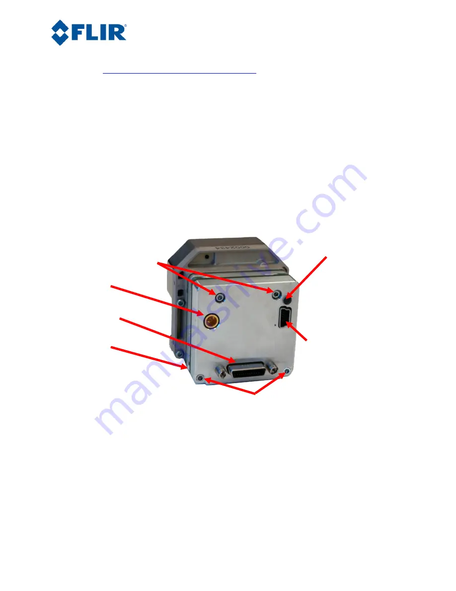
           Mounting Screws 
      M1.6 x 0.35 8 mm SHCS   


Power Status Light 


  MCX coaxial 
(analog video) 


Mini Camera Link 
   (digital video) 


        Spacer 
3 mm x 3.1 mm 


        Mini USB 


Mounting Screws 

M 1.6 x 0.35 x 16 mm 

Figure 1: Tau Camera Link Module installed on a Tau 640 camera 

The Camera Link Module takes CMOS-type digital data from the Tau camera and converts it to Camera 
Link. 

In order to use a Camera Link Module for acquisition of data, you will need to first enable the 

CMOS XP Bus Output using the FLIR Camera Controller. 

This option is found in the FLIR Camera 

Controller GUI under Video => Digital Video. In the Camera Controller GUI, you can select either 8-bit 
or 14-bit digital output.  

2.2


FLIR Camera Controller GUI 

The FLIR Camera Controller GUI provides communication between a PC and a Tau camera using either 
the USB interface or some other means of serial communication. 

Содержание Tau Camera Link

Страница 1: ...age 1 of 16 Tau Camera Link Module Operation and Modification Application Note FLIR Commercial Systems 70 Castilian Drive Goleta CA 93117 Phone 1 805 964 9797 www flir com Document Number 102 PS242 100 02 Version 100 Issue Date October 2011 ...

Страница 2: ...a Link Module installed on a Tau 640 camera 4 Figure 2 BNC to RCA Adapter 5 Figure 3 Device Manager showing proper driver installation 6 Figure 4 FLIR Camera Controller GUI Status Tab Not Connected 7 Figure 5 FLIR Camera Controller GUI Connection Window Part 1 7 Figure 6 FLIR Camera Controller GUI Connection Window Part 2 8 Figure 7 FLIR Camera Controller GUI Status Tab Connected 8 Figure 8 FLIR C...

Страница 3: ... Here is a sample of some of the resources that can be found Document Title Document Number Description Tau Quick Start Guide 102 PS242 01 Quick Start Guide for first time use FLIR Camera Controller GUI User s Guide 102 PS242 02 Detailed Descriptions for functions and adjustments for FLIR cameras using the FLIR Camera Controller GUI Tau 2 Product Specification 102 PS242 40 Product specification an...

Страница 4: ...es serial communication at either 57600 or 921600 Baud by creating a virtual COM Port on your computer for USB communications The Baud Rate is selected using auto Baud and the camera will communicate at the first Baud Rate in which it receives a command until it is powered off Mounting Screws M1 6 x 0 35 8 mm SHCS Power Status Light MCX coaxial analog video Mini Camera Link digital video Spacer 3 ...

Страница 5: ...ctions to the camera using the Camera Link Accessory Module 1 Plug the accessory directly into the rear of the camera There is a white 50 pin connector that will mate Use the included socket head cap screws to secure the expansion board to the camera These will insert on either side of the 50 pin connector The Camera Link module uses M1 6 0 35 8 mm screws Using longer screws could damage the camer...

Страница 6: ... example shows COM3 Figure 3 Device Manager showing proper driver installation 2 4 Software Connection This section describes simple communication with the camera using the FLIR Camera Controller GUI and assumes that the camera is connected to the PC using a USB cable and the Camera Link Accessory Module Please refer to the FLIR Camera Controller GUI User s Guide for more details on functionality ...

Страница 7: ...102 PS242 100 02 Rev100 October 2011 Page 7 of 16 Figure 4 FLIR Camera Controller GUI Status Tab Not Connected 3 Connect to the camera by selecting Tools Connection Figure 5 FLIR Camera Controller GUI Connection Window Part 1 1 3 2 ...

Страница 8: ... to retrieve the part number and serial number of your camera from this screen Figure 7 FLIR Camera Controller GUI Status Tab Connected 2 5 Digital Data via Camera Link This section describes digital data acquisition with the Camera Link accessory and assumes that all prior sections have been successfully completed 1 Connect one end of the Camera Link cable to the camera The camera connection is a...

Страница 9: ... Figure 8 FLIR Camera Controller GUI Digital Tab 3 Once you make these changes it is a good idea to save settings to make them power cycle persistent This can be done on the Setup Tab by clicking the Save Settings button 4 The digital data complies with Base Camera Link standards and will be compatible with most off the shelf Camera Link frame grabbers FLIR has tested the ImperX FrameLink Express ...

Страница 10: ...mera Link frame capture and so third party software must be used The ImperX frame grabber includes FrameLink Express software that allows for recording single or multiple images BMP JPG TIF and RAW as well as standard AVI clips Configuration requires selecting 1 TAP L R for the tap reconstruction selecting the same bit depth that you chose in the FLIR Camera Controller GUI in step 2 and clicking L...

Страница 11: ...the FLIR Camera Controller GUI Program can be instantiated using different ports so be sure the camera you are interested in controlling is actually connected to the physical port that was verified in the Device Manager in Section 3 2 step 5 Verify that the camera is powered by checking that the camera is producing an image on an analog monitor On cameras with a shutter installed listen for the so...

Страница 12: ... is no longer possible to communicate using USB It is recommended that only technicians with solder experience proceed with this modification and observe standard ESD practices 3 1Hardware Change You will first need to remove the cover by removing two screws on the bottom of the board and two jack screws on the Camera Link connector Figure 11 Philips screws to remove Figure 12 Jack Screws to remov...

Страница 13: ...Card 54 compliant and requires a 54 mm ExpressCard slot on a laptop or a PCI Adapter for use with a desktop computer An example for this is the Best Connectivity ExpressCard to PCI Express Conversion Card SD PEX EXPC For more information on the IMPERX frame grabber consult the manufacturer s website http www imperx com frame grabbers framelink express Using the FrameLink Express software that is p...

Страница 14: ...IR Camera Controller closed run FrameLink Express Virtual COM port which installs in the Program Files directory along with the FrameLink Express Software Select a COM Port that is currently unused This can be verified in the Device Manager under Ports Click Create Port and this virtual COM Port will remain accessible until it is deleted or this emulator is closed Figure 17 FrameLink Express Virtu...

Страница 15: ...a typical Camera Link interface cable flips the connector 180 degrees This means that pin 1 on the camera physically connects to pin 26 on the frame grabber 2 to 25 etc It is also important to note that connections need to be exactly made and not inverted For example SerTC_P on the camera needs to connect to SerTC_P on the frame grabber 4 0 External Sync The Camera Link accessory does not offer a ...

Страница 16: ... of 16 The metal case will also require modification to allow the wire to pass out A small hole can be drilled in the metal case to match the approximate location shown in the image of the camera assembly Figure 19 Ext Sync Header Connection Figure 20 External Sync Location ...

Отзывы: