Camera Link Module Accessory
102-PS242-100-02
Rev100
October 2011
Page 8 of 16
4.
Select Serial (RS-232), select 921600 as the Baud Rate for fastest communication, and click
Next. If you only have one serial communication port on your computer, the button will say
Finish.
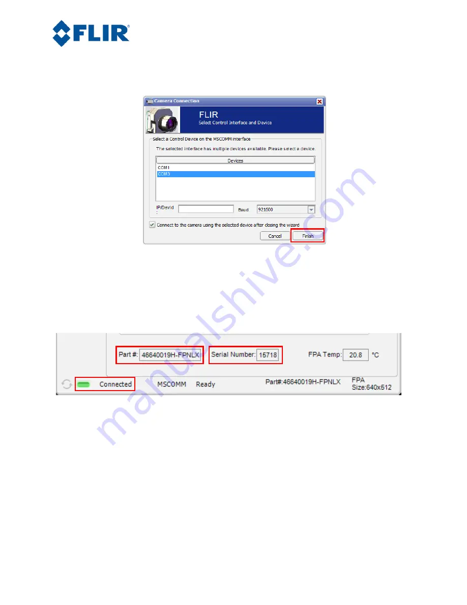
Figure 6: FLIR Camera Controller GUI Connection Window Part 2
5.
Select the Com port seen in the Device Manager and click Finish.
6.
The GUI will now automatically connect to the camera and refresh information in the software.
The status LED will turn green and it will display “Connected” on the bottom left. It is also
possible to retrieve the part number and serial number of your camera from this screen.
Figure 7: FLIR Camera Controller GUI Status Tab – Connected
2.5
Digital Data via Camera Link
This section describes digital data acquisition with the Camera Link accessory and assumes that all prior
sections have been successfully completed
1.
Connect one end of the Camera Link cable to the camera. The camera connection is a Mini-
Camera Link connector and frame grabbers may use either standard or Mini-Camera Link. It is
possible to purchase cables that have mini connectors on both ends or standard on one end with
mini on the other.
2.
The camera must be configured to output CMOS digital data in order for the Camera Link
accessory to work. This can be done by clicking “Video” on the left pane of the GUI, “Digital


