Camera Link Module Accessory
102-PS242-100-02
Rev100
October 2011
Page 15 of 16
3.3
Communication with other Frame Grabbers
Although FLIR has only validated communications with the IMPERX FrameLink Express, it may be
possible to use other models. A potential frame grabber would need to be capable of differential serial
communications at 57600 or 921600 baud. Camera Link communications standards call for a differential
serial connection and so the FLIR Camera Link Expansion Board includes a differential serial line driver
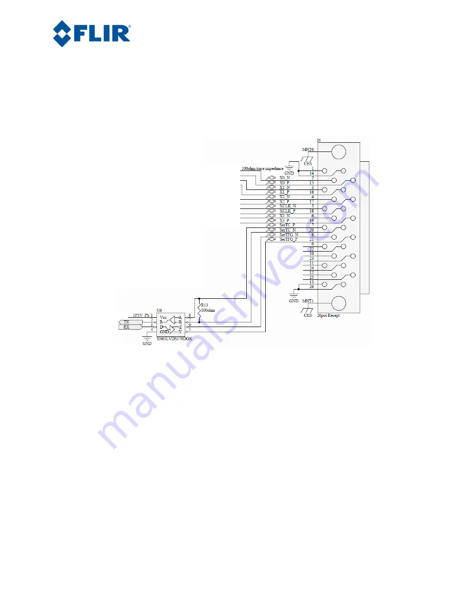
to convert signals to RS-232 type signals for the Tau core. The following schematic shows connections on
the FLIR Camera Link board and the line driver.
Figure 18: Electrical Schematic – Camera Link Connector on Camera Link Accessory
It is important to note that a typical Camera Link interface cable flips the connector 180 degrees. This
means that pin 1 on the camera physically connects to pin 26 on the frame grabber, 2 to 25, etc. It is also
important to note that connections need to be exactly made and not inverted. For example, SerTC_P on
the camera needs to connect to SerTC_P on the frame grabber.
4.0
External Sync
The Camera Link accessory does not offer a connection for External Sync by default, but it is possible to
access this with modification. There is a header connection point on the Camera Link Accessory board
which provides access to the XP13 pin. This connects directly to pin 21 on the Tau 50 pin Hirose
connector which is the External Sync. The connection point is through-hole #3 on the PCB. This is a
through-hole that will require soldering. Hole #1 is the leftmost hole and is square in shape. This is a
direct connection to the FPGA so the input levels should be 0V to 3.3V. There is no over-voltage or
reverse voltage protection.


