Flint & Walling © Copyright 2018. All rights reserved.
4
CONTROLLER LOCATION SELECTION
The NEMA 3R controller is intended for indoor and outdoor
use and for operation in ambient temperatures up to 125°
F (50° C) . It should be mounted in a location that provides
protection from water sprays greater than 30° from vertical .
The drive should only be accessed by trained and authorized
personnel . To ensure maximum weather protection, the
unit must be mounted vertically with the cover properly
aligned and secured with all lid screws . The following
recommendations will help in selection of the proper location
of the unit:
1 . A tank tee is recommended for mounting the tank,
pressure switch/transducer, pressure gauge, and
pressure relief valve at one junction . If a tank tee is not
used, the pressure switch/transducer should be located
within 6 ft . (1 .8 meters) of the pressure tank to minimize
pressure fluctuations . There should be no elbows
between the tank and pressure switch/transducer .
2 . The unit should be mounted on a sturdy supporting
structure such as a wall or supporting post - please
account for the fact that the unit weighs approximately 20
lbs .
3 . The electronics inside the controller are air-cooled . As a
result, there should be at least 6 inches of clearance on
each side and below the unit to allow room for air flow .
IL1721
Commander
®
Pro
Variable Speed
Controller
®
FW1629 A
COMMANDER
®
PRO
Variable Frequency Drive
www.getcommanderpro.com
FW1629 B
6.8366
2.7963
Notes do not print
Pressure
Tank
Pressure
Switch or
Transducer
Pump
Motor
Pressure
Relief Valve
Figure 2 Location Diagram
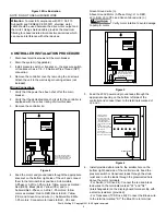
There should be at least 6 inches of
clearance on each side and below the unit to allow room
for proper air flow. There are to be no elbows between
the tank and pressure switch.
4 . The controller should only be mounted with the wiring
end oriented downward . If possible for best cooling,
the controller should not be placed in direct sunlight
or other locations subject to extreme temperatures or
humidity (mounting location should not be subjected to
condensation) .
5 . The mounting location should have access to 230V
electrical supply and to the submersible motor wiring .
6 . Do not expose the drive to water spray greater than 30°
from vertical .
Note: Installations that require larger than 6 AWG wire will
require an external junction box . Run 6 AWG from the drive
to the junction box and make external connections to the
appropriately sized wire with wire nuts .
WIRING SIZING CHART
Maximum Wire Lengths Connecting the Controller
to The Main Circuit Box
(Based On 3% Voltage Drop At 230V)
Motor
HP
Copper
Wire
Size
(AWG)
14
12
10
8
6
4
3
2
Circuit
Breaker
1 .5/2
Max .
Length .
(Ft .)
85* 140* 220 345 550 680 895 20 AMP
3
115* 180 285 455 560 740 25 AMP
5
115 185 290 360 470 40 AMP
* Wire with 90°C Insulation only
PUMP WIRING
If submersible pump type is chosen, the output of the drive is
3-phase . (If the option is available, 3-wire may be available
for submersible pumps) .
The power output terminals (for motor wire connections) are
located on the lower right-hand side of the controller and are
labeled RED, BLK, YEL and (
W
) . To select the wire size refer
to the pump owner’s manual, NEC and local codes for proper
wire size .
NOTICE: Regardless of owner’s manual, wire length should
not exceed 1000 ft .
If the Commander Pro Controller is used with above ground
motors the output is limited to 3-phase . To maximize motor
life the cable length between the controller and the motor
should be limited to a maximum length of 25 ft . Refer to the
pump owner’s manual, NEC and local codes for proper wire
size . Caution: Correct motor rotating needs to be verified to
avoid pump and motor damage .
Due to the inherent voltage changing
characteristics of variable frequency drives (VFD), there
is additional stress placed on the insulation of the wire
between the controller and the motor compared to a
standard pump system. Extra care must be taken when
using Un-jacketed Flat Parallel Pump Cable to ensure that
the insulation on each of the separated wires is the same
thickness. Care must also be taken to ensure a proper
seal with shrink tubing on any splices. Failure to take
these precautions can lead to “wire burn through” that
will shut down the system. Under these circumstances,
no permanent damage usually occurs to the controller or
motor. For further details call Technical Support at
800-742-5044.
SEPARATED WIRE


