


Flint & Walling © Copyright 2018. All rights reserved.
3
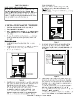
SYSTEM COMPONENTS
Please be sure that you have all major system components
necessary to properly install the submersible pump system .
Other components may also be necessary depending on the
application requirements .
1 . Submersible pump end
2 . Submersible motor
3 . Variable speed controller
4 . Pressure tank
5 . Pressure switch or transducer (packaged with controller)
6 . Pressure relief valve (purchased separately)
7 . Pressure gauge (purchased separately)
PIPING
General Information
The system is capable of flows up to 40 GPM . Discharge
piping is recommended to be 1 .25” for installations in which
flows will exceed 12 GPM . The use of smaller pipe will
increase friction losses and can severely limit the maximum
capacity of the system .
This pump may be capable of pressures exceeding 325 PSI
under maximum conditions, select pipe accordingly . Consult
your pipe supplier to determine the best pipe material for the
installation
Pump Inspection
Prior to installation check the pump, motor, controller and tank
for shipment damage .
Pressure Tank
The Air-E-Tainer® tank supplied with your system has a
factory set pre-charge of 35 PSI . Installer must recheck to
make sure tank is still 35 PSI . This is 70% of the factory
preset operating pressure of 50 PSI . Any change in operating
system pressure will require that the pre charge in the tank
be modified to 70% of that pressure . See Tank Table for
minimum pressure tank size .
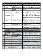
MINIMUM PRESSURE TANK SIZE (TOTAL
CAPACITY)
Controller
Pump Flow
Rating less
than 12 GPM
Pump Flow
Rating 12 GPM or
higher
VS15/TVS15
4 .6 Gal (132477)
4 .6 Gal (132477)
VS20/TVS20
4 .6 Gal (132477)
14 Gal (132661)
VS30/TVS30
14 Gal (132661)
14 Gal (132661)
TVS50
14 Gal (132661)
20 Gal (132662)
Many pumps can develop excessive
pressure, resulting in equipment and property damage
as well as possible injury. Always install a pressure relief
valve capable of passing full pump flow at 100 PSI. Install
the pressure relief valve between the pump and pressure
tank.
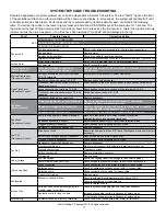
PRESSURE SETTING GUIDE
System Pressure
(at Pressure Sensor)
Pressure Tank Setting
(PSI) (+/- 2 psi)
25
18
30
21
35
25
40
28
45
32
50 (factory set)
35
55
39
60
42
65
46
70
49
75
53
80
56
Pressure Relief Valve
The pressure relief valve and the discharge outlet need a
flow rating which exceeds the flow capacity of the installation
at the relief pressure . When located in an area where a water
leak or relief valve blow-off may damage property connect
an adequate drain line to the pressure relief valve . Run the
line to a suitable drain or to an area where the water will not
damage property .
Not providing an adequate relief valve
can cause extreme overpressure which could result in
personal and/or property damage. It is recommended
that you manually activate the valve monthly to keep it in
good working order.
Discharge Pipe
When discharge piping requires an adapter it is
recommended that a stainless steel adapter be used .
Galvanized fittings or pipe should not be connected directly
to the stainless steel discharge head of the pump as galvanic
corrosion may occur . Barb type connectors should always
be double clamped . Torque arrestors are not required on this
installation due to the soft starting characteristics of the motor
and controller
Check Valve
A check valve is factory installed in the discharge head of the
submersible pump . This maintains water within the pipe when
the pump is not operating . For well depths exceeding 100
feet, an additional check valve should be installed every 100
feet .
Safety Rope
A safety rope eyelet is provided at the discharge of the pump .
It is recommended to attach a nylon safety rope . This will
assist in the removal of the pump and also prevent loss of
the unit in the bottom of the well due to a loose fitting or pipe
deterioration .