321037
45
10 WATER
DISPENSER
10.1
Pressure Dispensing Pad
This pad is located at the rear of the dispensing area and is used to dispense water. Water can be
dispensed by pressing the dispenser pad. The display will light up and the water fill icon will
appear when the water is dispensed.
The dispenser will not operate while the PC door is open.
10.2 Initial
Use
Press the glass or container into the pressure-dispensing pad.
Note: Pressing very hard against the water dispensing pad will NOT make the water dispenser
operate any faster or produce greater quantities of water.
Initially allow approximately a one-minute delay from when the pressure-dispensing pad is pushed
until the water is dispensed. While the tank is filling, no water sign will appear.
Dispense at least 8 – 10 litres (8 – 10 quarts) of water through the system, stopping intermittently
to ensure that air in the tank is flushed out. Failure to do so will result in excessive dripping from
the dispenser.
10.3
Water Filter and Cartridge
The product is supplied with a water filter and cartridge located in the upper right hand side of the
provision compartment. A bypass cap is also supplied should the customer wish to use the water
system minus the filter cartridge.
The filter replacement icon will appear and blink when the filter needs to be replaced. This is
approximately every 2800 litres of water or 6 months.
10.3.1
Installing the Water Filter
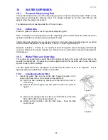
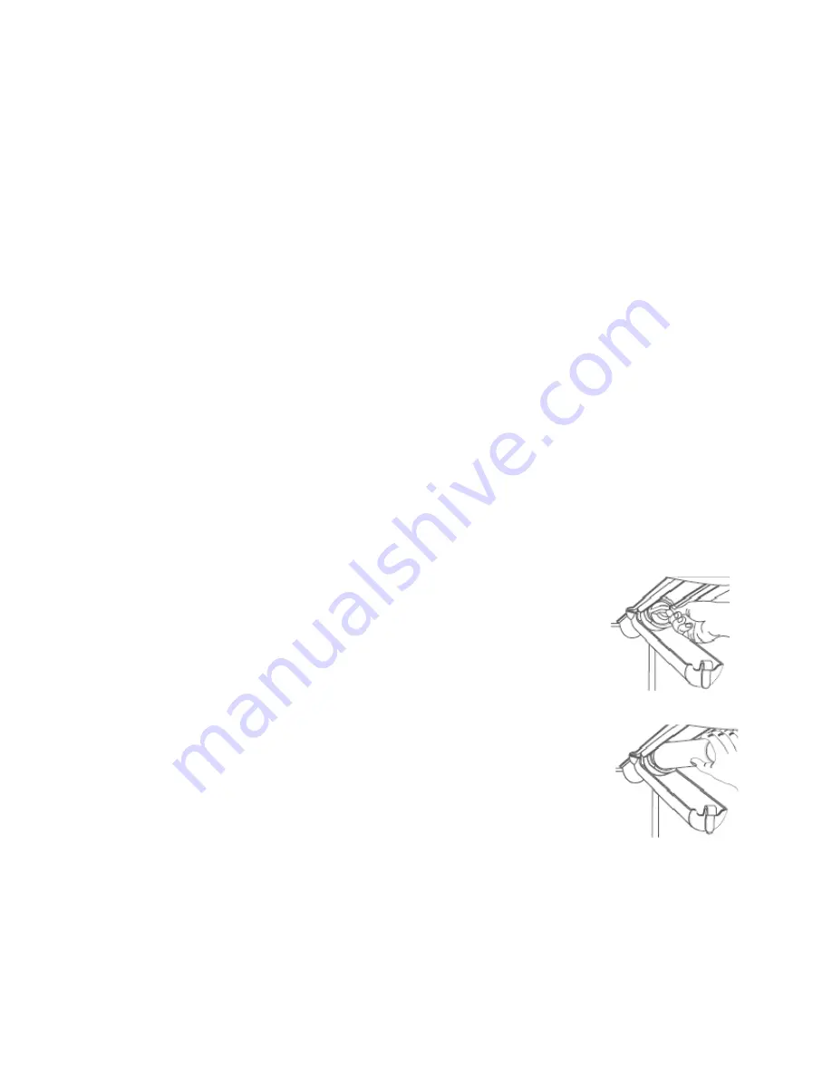
1. Install the water filter into the water filter housing located in the
upper right-hand corner of the provision compartment:
(a) Open the filter housing by pressing the tab at the front end of
the housing.
(b) Remove the blue bypass cap and retain for later use (refer to
figure 1).
Figure 1
(c) Remove the sealing label from the end of the filter and insert the
filter into the filter head (refer to figure 2).
(d) Rotate gently clockwise until the filter stops. Snap the filter
cover closed.
Figure 2
Содержание RF175W
Страница 1: ...321037 Service Manual Active Smart Refrigerator Freezer Models RF195A RF175W...
Страница 19: ...321037 19 5 4 5 Condenser Mullion Layout Diagram 5 4 5...
Страница 77: ...321037 77 15 WIRING DIAGRAM 15 1 RF175 Wiring Diagram...
Страница 78: ...321037 78 15 2 RF175 Control Module Wiring Diagram...
Страница 79: ...321037 79 15 3 RF175 Ice Water Wiring Diagram...
Страница 80: ...321037 80 15 4 RF175 Ice Water Control Module Wiring Diagram...
Страница 81: ...321037 81 15 5 RF195A Ice Water Wiring Diagram...
Страница 82: ...321037 82 15 6 RF195A Ice Water Control Module Wiring Diagram...


