321037
42
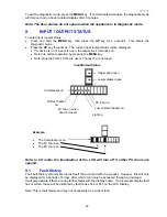
Input/Output Status
Press the
UP
key once more – Input/Output status.
IO
shown indicates the product is in input/output status. The LCDs that are highlighted indicate
what components are on.
Note: When the PC door is opened, the backlight will turn off. The LCD for the FC or PC door will
come on when either door is opened.
The IO shown stands for Input/Output, not a temperature.
Diagram D
Input/Output Status
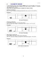
PC2 Sensor Temperature
Press the
UP
key once more – PC2 sensor. This sensor is attached to the water tank.
Note: 5.0 shown indicates the temperature of the PC2 sensor is 5
O
C (41
O
F).
Diagram E
PC Sensor 2
PC2 Sensor Temperature
Press the
UP
key once more – Icemaker sensor.
Note: 12.0 min shown indicates the temperature of the Icemaker sensor is –12
O
C (10.4
O
F).
Diagram F
Icemaker Sensor
Fault History
Press the
UP
key once more – Fault History.
HOO
will be showing.
Diagram G
Fault History
Содержание RF175W
Страница 1: ...321037 Service Manual Active Smart Refrigerator Freezer Models RF195A RF175W...
Страница 19: ...321037 19 5 4 5 Condenser Mullion Layout Diagram 5 4 5...
Страница 77: ...321037 77 15 WIRING DIAGRAM 15 1 RF175 Wiring Diagram...
Страница 78: ...321037 78 15 2 RF175 Control Module Wiring Diagram...
Страница 79: ...321037 79 15 3 RF175 Ice Water Wiring Diagram...
Страница 80: ...321037 80 15 4 RF175 Ice Water Control Module Wiring Diagram...
Страница 81: ...321037 81 15 5 RF195A Ice Water Wiring Diagram...
Страница 82: ...321037 82 15 6 RF195A Ice Water Control Module Wiring Diagram...


