background image

321037


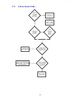
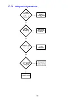
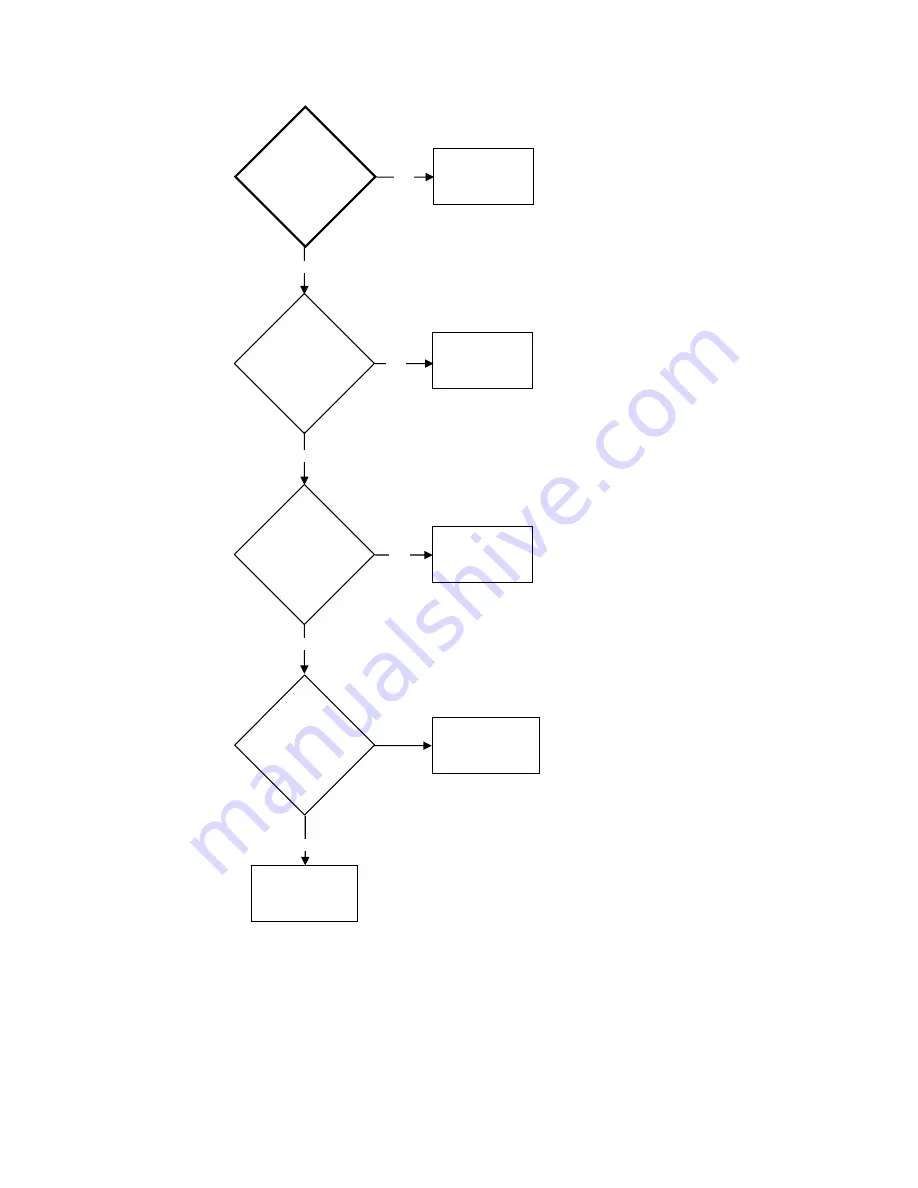
100 

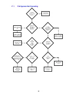
Are the 

compartment 
temperatures 

set correctly? 

Wait until 

refrigerator 

completes defrost 

cycle.


Adjust settings. 

Advise customer 

product OK. 


Check 

temperatures. 

Check compressor 

and system for 

leaks/blockage and 

repair as required. 

Yes 

Yes 

No

No 

No


Remove FC cover. 

Is there a full frost 

pattern on the 

evaporator?


Yes


Should the 

compressor be 

running? (Check 

defrost and cycle 

temperatures) 


Is there power to 
the compressor? 

Refer Section  

14.1 


Repair as required. 

No 

Yes

17.14 

Refrigeration System Faults 


Содержание RF175W

Страница 1: ...321037 Service Manual Active Smart Refrigerator Freezer Models RF195A RF175W...

Страница 2: ...t to change without notice Note A service summary may be found within a plastic bag wedged into the right hand side of the condenser located behind the front toe kick panel of the refrigerator CA NUMB...

Страница 3: ...7 5 4 1 Condensate Disposal 17 5 4 2 Filter Drier 17 5 4 3 Condenser 18 5 4 4 Condenser Fan 18 5 4 5 Condenser Mullion Layout 19 5 4 6 Compressor Compartment Layout 20 5 5 FC Mullion Heater 20 5 6 Pro...

Страница 4: ...Filter 45 10 4 To Reset the Filter Icon 46 10 5 To Disable the Filter Alarm 46 11 SERVICING PROCEDURES 47 11 1 Safety Considerations 47 11 2 Electrical Safety Test 47 11 3 Door and Door Gasket 48 11...

Страница 5: ...GRAM 77 15 1 RF175 Wiring Diagram 77 15 2 RF175 Control Module Wiring Diagram 78 15 3 RF175 Ice Water Wiring Diagram 79 15 4 RF175 Ice Water Control Module Wiring Diagram 80 15 5 RF195A Ice Water Wiri...

Страница 6: ...TRONICS Display Module Ice Water Part No 819415P Display Module Non Ice Water Part No 881219P Power Control Module Part No 860524P SUCTION LINE ASSEMBLY Part Number 817864 DEFROST ELEMENT Part Number...

Страница 7: ...ency 60 Hz Flapper Heater 12 volt 10 watt 15 ohms Duct Heater 12 volt 3 watt 48 ohms Low Ambient Heater 12 volt 7 watt 22 ohms Ice Tube Heater 12 volt 1 2 watt 120 ohms Defrost Element 110 volts 355 w...

Страница 8: ...c Right Hand Door Hinging Ice Water Colour M Iridium X S S Ezkleen Iteration Brand Market RF 175 W C R U X 1 FP US Market USA Brand Fisher Paykel Iteration 1 Colour Stainless Steel Ice Water Door Hing...

Страница 9: ...eful with heat guns 3 2 2 Environmental Health and Safety When servicing products consider safety and health issues and requirements which must be adhered to at all times Specific safety issues are 1...

Страница 10: ...e back 4 2 Levelling Components Front and rear rollers are fitted ex factory Cabinet levelling can be done by adjustment of the front roller levelling screw See diagram 4 2 Weight should be lifted off...

Страница 11: ...321037 11 Diagram 4 3 Toe Grill Installation Diagram 4 4 Uneven Door Alignment RF195A only Adjust levelling foot to adjust door alignment...

Страница 12: ...ere both doors will close with the aid of the door closing components It is also important that the appliance sits solidly on the floor Cabinet levelling can be done by adjustment of the front roller...

Страница 13: ...e the material on the floor against the wall and push the product on top of the material Unlevelled floors Gently push the top of the refrigerator back until the rear rollers contact the floor Measure...

Страница 14: ...vaporator brazed in the FC POWER CONTROL MODULE Contains the microprocessor that controls all functions of the refrigerator and gathers data from the sensors This module also contains support circuitr...

Страница 15: ...T DEFROST ELEMENT COMPRESSOR BOTH PC FC TURNS OFF TURNS ON TURNS OFF TURNS ON FANS TURN ON DEFROST TIME TARGET IS 18 MINUTES MAXIMUM IS 40 MINUTES NORMAL RUN 2 MINUTES 4 MINUTES 30 SEC BACK TO NORMAL...

Страница 16: ...high pressure gas has been condensed the liquid refrigerant flows through the capillary tube which is soldered to the suction line as a heat exchanger entering the evaporator mounted in the freezer co...

Страница 17: ...am 5 4 1 5 4 2 Filter Drier Diagram 5 4 2 The filter drier or molecular sieve as the name suggests is both a filter and a drier Whenever a system is opened it is essential that the filter drier is rep...

Страница 18: ...an that is located alongside the compressor in the unit compartment It is important that the condenser is cleaned from time to time as any restriction to air flow will affect the overall operating per...

Страница 19: ...321037 19 5 4 5 Condenser Mullion Layout Diagram 5 4 5...

Страница 20: ...er 8 Filter process pipe 5 5 FC Mullion Heater The mullion heater is part of the condenser copper tubing mullion heater providing heat to the gasket area of the FC compartment preventing sweating of t...

Страница 21: ...321037 21 Diagram 5 6 User interface Non ice water models Polystyrene insulation Polystyrene insulation Water tank cover Ice water models PC duct cover...

Страница 22: ...e back to the FC evaporator The PC fan motor is housed in the back edge of the divider The divider partition also houses the low ambient heater and the reed switches located in the front of the cross...

Страница 23: ...controlled by pulse width modulation PWM The power control module controls the fan motor speeds by driving them with short pulses These pulses vary in duration to change the speed of the motor The lo...

Страница 24: ...e wiring harness of the defrost element having a tripping temperature of 72O C 161 6O F Once open circuit they cannot be reset Replacement is part of the element heater assembly These fuses in both le...

Страница 25: ...ezer compartment fan will always be set at the maximum FC fan speed with the PC fan being adjusted to meet the requirement of that compartment Off cycle fans OCF operate when the product cycles off wi...

Страница 26: ...horten its life 6 1 8 Thermistor Temperature Sensors These sensors are used to monitor temperatures within the refrigerator There are three 1 Defrost sensor mounted above the evaporator used to measur...

Страница 27: ...0 3 935 15 0 3 217 20 0 2 644 25 0 2 186 30 0 1 817 35 0 1 518 40 0 1 274 45 0 1 075 50 0 0 9106 Table 6 1 8 6 1 9 Flapper Door Heater Used on the French door models to warm the flapper that seals the...

Страница 28: ...Chill Temperature Ice and Settings Arrow Keys The ARROW keys are used to scroll through the settings of each function Lock The LOCK key enables and disables the water dispenser and all the buttons 7 2...

Страница 29: ...o its coldest temperature set point for a 12 hour period To access use the MENU button to scroll to FREEZER then use the up or down key to get fast freeze To deactivate manually use the MENU button an...

Страница 30: ...all the buttons To activate this mode press the LOCK key for 4 seconds 7 4 9 Filter Replacement Alert This icon will appear when the water filter needs changing The filter needs replacing every 2800 L...

Страница 31: ...amount of ice is required To manually force a harvest Press the Down UP and Lock buttons together and hold for 4 seconds The icemaker will rotate and empty the contents of the ice tray then return to...

Страница 32: ...eezing It is connected in series with the low ambient heater 7 6 Key Presses To activate any mode certain combinations of key presses are required The key presses are as follows Key presses used by th...

Страница 33: ...C Setting 21 5 O C 21 0 O C 20 O C 19 5 O C 18 5 O C 18 0 O C 17 0 O C 16 5 O C 15 5 O C 15 O C 14 0 O C 6 7 O F 5 8 O F 4 O F 3 1 O F 1 3 O F 0 4 O F 1 4 O F 2 3 O F 4 1 O F 5 O F 6 8 O F Colder Warm...

Страница 34: ...r fan which supplies the cold air into the PC compartment The amount of air is controlled electronically by two sensors which in turn regulate through the power control module the speed of both PC and...

Страница 35: ...evious 2 defrosts were aborted after 40 minutes Primary Action Check defrost element assembly in the FC If faulty replace Fault Code 3 Reason The resistance of all the temperature sensors are outside...

Страница 36: ...tion Check the 6 way fan LAH RAST connector at the power module Secondary Action Re terminate the 6 way fan LAH RAST connector Tertiary Action Replace control module Fault Code 12 Reason The current m...

Страница 37: ...ons at both the fan and the power module Secondary Action Check the fan If faulty replace Fault Code 19 Reserved Fault Code 20 Reason The flapper heater current is low Primary Action Check the Molex c...

Страница 38: ...if faulty Fault Code 29 Reason the icemaker solenoid current is low Primary Action Check the connection to the solenoid Check the resistance of the solenoid Secondary Action Correct loose connections...

Страница 39: ...n load using Smart tool Reason The PC return duct heater current is too high Primary Action Check for short circuit of PC return duct heater Check the resistance of the heater Secondary Action Replace...

Страница 40: ...istance 37 5 If the icemaker sensor needs to be replaced refer to Section 11 4 16 7 13 Testing Water Valve The water valves are located in the unit compartment Disconnect the refrigerator from the pow...

Страница 41: ...Temperature Note 4 0 shown on display indicates the temperature of the pc sensor is 4 0O C 39 2O F Diagram A PC Sensor Temperature FC Sensor Temperature Press the UP key once more FC sensor temperatu...

Страница 42: ...ds for Input Output not a temperature Diagram D Input Output Status PC2 Sensor Temperature Press the UP key once more PC2 sensor This sensor is attached to the water tank Note 5 0 shown indicates the...

Страница 43: ...s are used The last 5 are not used Input Output Status Example The Compressor is on The FC fan is on The PC fan is on Note In I O mode the illumination of the LCD will turn off if either PC doors are...

Страница 44: ...lly Force the Icemaker Press LOCK key first then press the DOWN and UP keys and hold all three keys for 4 seconds This will activate the icemaker Note If the bins are removed to observe the icemaker o...

Страница 45: ...ensure that air in the tank is flushed out Failure to do so will result in excessive dripping from the dispenser 10 3 Water Filter and Cartridge The product is supplied with a water filter and cartri...

Страница 46: ...e Discard the first bin of ice made Please note that once installation is complete a few drips of water may appear out of the dispenser over the next few days as the remaining trapped air is cleared T...

Страница 47: ...f the electrical circuit is serviced or disturbed in the course of carrying out service adjustments or procedures it is essential that an insulation and earth continuity test be carried out using a tw...

Страница 48: ...le part of the door It is held in place against the door liner by means of a moulding that locks the gasket in place once pushed into it There are no screws or retainers to remove or fit To Remove the...

Страница 49: ...xpose the back 6 Remove the PC sensor from the cover and cut off the sensor wires as close to the sensor as possible 7 Replacement of the new sensor is done by cutting the wire off the new sensor abou...

Страница 50: ...1 4 5 Replacing Cross Base Rail Reed Switches 1 Unplug the refrigerator from the outlet socket 2 Remove the reed switch cover by placing a small bladed screwdriver into the slot under the cover and li...

Страница 51: ...he connector 9 Remove the end deflectors from both ends of the evaporator 10 Using long nose pliers bend the aluminium tabs to remove the defrost element 11 Remove the thermal fuses from the air defle...

Страница 52: ...ket mount slides as shown in photo 11 4 10 3 Once the tabs have been released the FC drawer can be lifted up 4 Locating tabs on the bracket mount slides need to be removed out of the slide to remove t...

Страница 53: ...as shown in step 2 4 Fit the anti racking bar into the wracking pinion gear ready to fit to the drawer 5 Both anti racking pinion gears need to be fitted simultaneously If this is not achieved damage...

Страница 54: ...bins trays from the freezer and remove the FC drawer 3 Remove the left hand side rail supports 4 Remove the clip and insulation pad holding the icemaker sensor from the bottom of the icemaker tray 5 R...

Страница 55: ...g clips are to be pushed in to remove cap Photo 11 4 14 1 5 Remove the top screws holding the top flapper hinge to the door liner Refer to photo 11 4 14 2 Second screw located in front of hinge Photo...

Страница 56: ...is turned off at the supply tap 2 Disconnect the refrigerator from the power supply 3 Pull the product away from the wall to access the rear of the product 4 To remove the water tube from the water v...

Страница 57: ...lastic bag but do NOT touch the bulb with your fingers 5 Push the bulb into position 6 Reconnect the refrigerator to the power supply 7 Ensure the light operates and refit the light cover 11 4 20 Repl...

Страница 58: ...allow depth Cut bend or break off the 2 lugs on the outer edge of the lamp housing as shown below 4 Drill two shallow 4mm deep 5mm holes in the concave of the lamp housing at the 5 10 o clock position...

Страница 59: ...ss then slide heat shrink over the new lamp harness Crimp to the existing harness using butt connectors or by soldering each joint Insulate the joint with the heat shrink Note It is important that goo...

Страница 60: ...a female block connector cut the wire end square and insert it into the correct location on the block connector itself With the wire fully inserted apply pressure to the terminal which will lock the...

Страница 61: ...1138 0200 MLX 51138 0600 MLX 881593 855411 Plug Pin 16 22AWG 50599 8100 MLX 20 26AWG 50600 8100 MLX There are two sizes of terminals to suit the wire Gauges 881597 881598 Retainer 51140 0205 MLX 88159...

Страница 62: ...t coded or indexed Part Number 2 way 3 way 873251 4 way 873250 5 way Not currently used 6 way 873247 7 way Not currently used 8 way 873279 9 way 819301 10 way 873248 11 way 819300 12 way 873243 13 way...

Страница 63: ...There are two sizes of terminals to suit the wire Gauges 819607 819608 Retainers Common to both plugs sockets 2 way 3 way 4 way YLS 02V YLS 03V YLS 04V 819620 819621 819622 Socket 2 pin 3 pin 4 pin 6...

Страница 64: ...motors fitted with either the earlier Mini Mate N Lok plug or the later Molex plug Parts required are Component Qty Part Number Mini Mate N Lok 2 way housing plug 1 873988 Pin Connector 2 872957 Mole...

Страница 65: ...f the icemaker does a manual harvest do you hear or see water entering the ice mould tray See Note 5 10 Failure to produce ice can be related to the fact that the FC compartment is not cold enough The...

Страница 66: ...ilt up around it This could be the reason why it doesn t rotate Check that the evaporator is defrosting and the defrost element is working along with the FC fan If not thaw and retest Force a manual h...

Страница 67: ...f testing the icemaker unit is to use a 9 volt battery plus battery terminal and a multi meter With the meter probes placed into the back of the icemaker 4 way socket onto the yellow and blue wires ch...

Страница 68: ...er Panel RF195A When refitting the front dispenser panel it is important that the wiring harness is placed correctly to avoid it being pinched otherwise it will prevent the panel from sitting flat whe...

Страница 69: ...e Pressure Gauge Step 1 Cut and connect the pipe circuit to be tested to the in line pressure gauge and braze this joint Step 2 At the other end of the pipe circuit being tested crimp off the pipe wit...

Страница 70: ...s a leak may not be found by pressurising the circuit whereas a vacuum pulled on the same circuit will show the leak Keep this in mind as oil within the circuit can block a hole In some cases if the b...

Страница 71: ...suction pipes on the compressor uppermost Refer diagram 13 1 1 Diagram 13 1 1 Note We mark all our refrigerator and freezer cartons with a number of stars on one side of the carton If the product is...

Страница 72: ...nt to keep the thermal fuse in the element circuit away from the heat gun as heat from the heat gun can cause the thermal fuse to go open circuit 13 3 Refilling a Void In Foam Insulation When 50ml of...

Страница 73: ...Measure chemicals by weight only and NOT by volume Not essential for small quantities used for filling voids after repair c Avoid contact with skin or clothing d Use only in accordance with the recom...

Страница 74: ...workshop fixed and or portable ducting with exhaust fans can provide good ventilation In a customer s house various alternatives are possible a A portable ducted fan exhausting to the open air b Turn...

Страница 75: ...pressor mounting pins and lift the compressor clear of the unit compartment Seal the compressor lines 7 Fit the new compressor to the mounting pins and refit the retaining clips 8 Refit the piping suc...

Страница 76: ...an off cycle 14 3 Compressor starts runs and then stops Possible Causes 1 Low voltage high voltage 2 Check the compressor voltage matches the supply voltage 3 The system may be grossly overcharged Li...

Страница 77: ...321037 77 15 WIRING DIAGRAM 15 1 RF175 Wiring Diagram...

Страница 78: ...321037 78 15 2 RF175 Control Module Wiring Diagram...

Страница 79: ...321037 79 15 3 RF175 Ice Water Wiring Diagram...

Страница 80: ...321037 80 15 4 RF175 Ice Water Control Module Wiring Diagram...

Страница 81: ...321037 81 15 5 RF195A Ice Water Wiring Diagram...

Страница 82: ...321037 82 15 6 RF195A Ice Water Control Module Wiring Diagram...

Страница 83: ...Check for broken wires Total Compartment Too Cold FC fan not going Check I O Fault Log Check power to plug Check for broken wires Check polarity Replace fan Short of gas Check run percentage if high...

Страница 84: ...cation Check set temperature Sensor clipped and located in correct position Faulty sensor Check calibration of sensor ice point using interface binary or refer to thermistor resistance table in servic...

Страница 85: ...pressing buttons If no click check power control module If click heard check the defrost heater 230v output at the power control module Sensors Check display for fault codes 0 to 5 Sensors above or be...

Страница 86: ...r on display module Noisy Fan PC Ice around gasket Replace assembly with new fan kit Wires touching Tuck wires away from fan blade Faulty fan replace assy with new fan kit Fit replacement Noisy Fan FC...

Страница 87: ...need to be installed Remove tube from exit of filter and test the water for taste after the filter If taste is present replace filter On Installation No Water Coming In Water supply not turned on Pre...

Страница 88: ...o Cold PC Too Warm 17 5 PC Too Cold 17 6 Ice Condensation Forming 17 7 No Light 17 8 Door Switch Not Operating 17 9 Defrost Heater Faults 17 10 Compressor Faults 17 11 Compressor Runs Continuously 17...

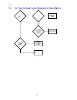
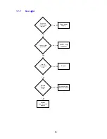
Страница 89: ...outlet socket No Yes Is the connector fitted correctly to display Is there 12V DC between the power control module the LCD display No Is there power to the power control module Does the LCD display li...

Страница 90: ...ir or replace faulty components Replace power control module Is there power to the refrigerator PC light LCD Display Fault in house wiring No Is there power to the house outlet socket Yes Yes No Repai...

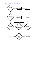
Страница 91: ...vailable Refer to Section 17 10 Refer to Section 7 10 Repair or replace faulty components Are temperature settings correct Are temperatures of contents of PC FC OK Advise customer temperatures OK Advi...

Страница 92: ...ctly Is Smart Tool download available Refer to Section 7 10 Repair or replace faulty components Are temperature settings correct Check door gasket sealing is OK Install components correctly sealing an...

Страница 93: ...ts of PC frozen Is Smart Tool download available Refer to Section 7 10 Repair or replace faulty components Are temperature settings correct Check assembly of all ducts covers Check for blockages in ai...

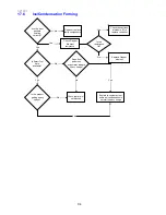
Страница 94: ...Check that drain is not blocked Are the door gaskets sealing correctly Explain to customer that some ice condensation is normal in heavy usage situations Is the product getting heavy usage No No No No...

Страница 95: ...Does the LCD Display light up Check is light bulb OK Check power supply Replace faulty component Repair Replace power control module Repair replace faulty component Refer to Section OK Yes No Yes Yes...

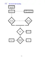
Страница 96: ...ata download will verify door switch failures by very high door open counts V actual openings Replace reed switch Repair Yes No Yes No Does FC door L E D switch on off as FC door is opened and closed...

Страница 97: ...place faulty components Advise customer no fault found Check correct operation of defrost heater Check location of defrost sensor Check if door has been left ajar Yes No Repair replace faulty componen...

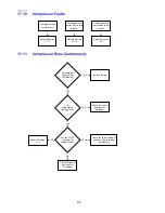
Страница 98: ...continuously Are there any faults on the LCD display Is refrigeration taking place Continue testing Check for loss of gas leak or blockage Check for correct fitting of sensors Check sensor resistances...

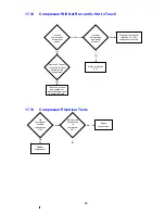
Страница 99: ...es Check compressor and system for leaks blockages and repair as required Yes No Remove FC cover Is there a full frost pattern on the evaporator Yes No 17 12 Compressor Will Not Run and is Hot to Touc...

Страница 100: ...ck temperatures Check compressor and system for leaks blockage and repair as required Yes Yes No No No Remove FC cover Is there a full frost pattern on the evaporator Yes Should the compressor be runn...

Страница 101: ...resistance Is it correct to specs Replace water valve Turn tap back on again and check water flow from tube Turn tap off disconnect water tube at water valve Does water come out of tube Replace water...

Страница 102: ...eck Refit lever and test Is the lever detect in place Yes Yes No No Yes Is the Ice tray filling with water Yes Force a harvest and check if tray fills Check FC temperature Has FC reached 8 C No Invest...

Отзывы: