background image

Page | 10  

-


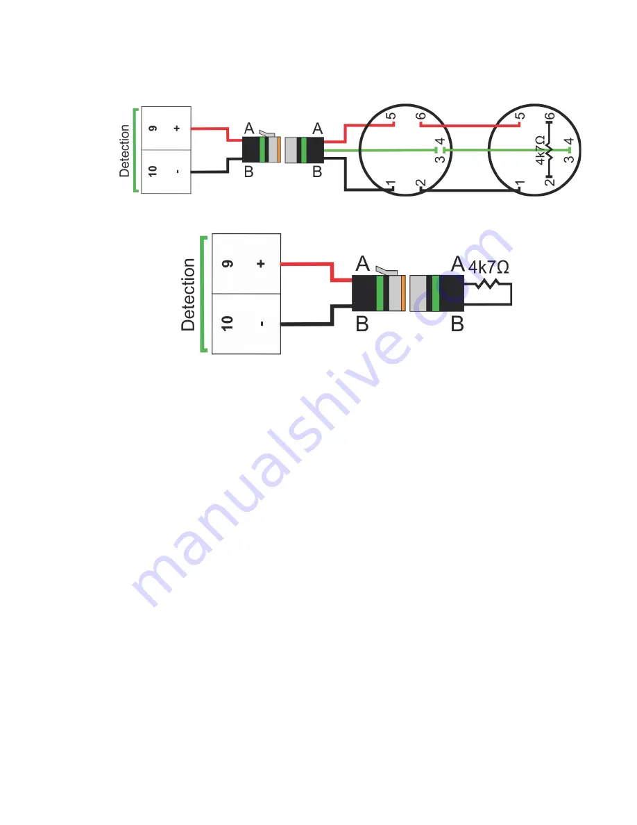
Conventional Detector (Thermal / Smoke):  

Conventional Detector


(P/N FP-08920 

Thermal / FP-94140 Smoke) can be connected together in quantities up to 30.  A 4k7

Ω 

End-of-line resistor must be installed in the last detector in the circuit.


-


Detection Not Used:

 If detection is not used, the supplied end-of-line plugs (marked 

green) must be connected to the Circuit 1 Alarm output.


5.


Circuit  2  Alarm  Circuit:   

This  circuit  is

  ALARM  ONLY 

and  will  only  operate  the 

siren/strobe.  Connections for detection and manual call points are the same as Circuit 1 
Alarm.  If detection is not used, the supplied end-of-line plugs (marked green) must be 
connected to the Circuit 2 Alarm output. 

6.


Discharge  Circuit:   

This  circuit  should  remain  disconnected  until  all  other  circuits  are 

connected.  The control panel 

must not

 be in an alarm/fault condition when the FirePro 

generators are connected, as this may cause an accidental discharge.  A Universal Test 
Lamp (P/N FP-08800) should be connected to take the control panel out of fault condition 
and for any commissioning.


-


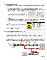
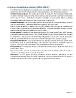
Mounting  FirePro  Generators: 

FirePro  Generators  must  be  installed  using  only 

approved brackets 

with observation of the relevant stream lengths and thermal 

clearances

 noted in the design calculation and risk assessment.  Generators should be 

mounted near the top of the risk area, with care taken to aim generators away from 
openings or obstacles that may impede dispersion of the suppression agent.  Egress 
routes  for  personnel  must  be  kept  clear,  and  not  be  obstructed  by  any  installed 
components or by agent dispersion. 


Содержание FP-08450

Страница 1: ...Fire Detection and Activation System Model 08450 Rev 2 7...

Страница 2: ...s 7 3 9 Connecting Multiple FirePro Generators 7 4 Installation 8 5 Wiring Diagram 12 6 Programming 13 7 Operation 13 7 1 LED Indicators 13 7 2 Isolate Function 13 7 3 Reset Function 14 7 4 Test Funct...

Страница 3: ...1 3 In Case of Fire If a fire occurs equipment operators should do the following 1 Detection will initiate an alarm condition on the FirePro System 2 The siren strobe will operate and if shutdown rel...

Страница 4: ...cted from Stainless Steel Comes with installed Deutsch Plug for easy install FP 6100 Heavy Duty Bracket 316 SS Suits FP 1200 2000 3000 5700 FirePro Aerosol Generators Detection Circuit Circuit 1 Alarm...

Страница 5: ...wer source 3 3 Siren Strobe Output A siren is required for all marine installations The recommended siren strobe is the Flashni Xenon Sounder Beacon In a typical install the maximum number of supporte...

Страница 6: ...The Circuit 2 Alarm Output is a zoned detection circuit capable of operating up to 30 conventional detectors 100 metres of linear heat detection cable or 30 manual call points The Circuit 2 Alarm Out...

Страница 7: ...he back of the plug Cables are colour coded for easy identification When installing system cables should be only connected to the correctly coded cable Colour Coding for cables is as follows 3 9 Conne...

Страница 8: ...ain Power When panel has been mounted in a suitable location connect main supply power using a Lead to the power input marked red The recommended source for the main power supply input is the vessel s...

Страница 9: ...ircuit can be programmed for ALARM ONLY operate siren strobe or AUTOMATIC DISCHARGE discharges suppression system and operates siren strobe If detection is not used the supplied end of line plugs mark...

Страница 10: ...ircuit This circuit should remain disconnected until all other circuits are connected The control panel must not be in an alarm fault condition when the FirePro generators are connected as this may ca...

Страница 11: ...utput they must be connected using the FP 08919 Splitter Lead See 3 4 Discharge Output for design considerations when connecting multiple FirePro generators The maximum number of FirePro Generators th...

Страница 12: ...Page 12 5 Wiring Diagram...

Страница 13: ...el Discharging System has initiated activation sequence 7 2 Isolate Function To isolate the control panel press and hold Mode Switch 1 until a 1 beep is heard and the Isolated LED is illuminated To re...

Страница 14: ...el to normal operation The test function does not activate the suppression system Note If any LEDS or siren strobes do not operate contact your supplier 7 5 Discharging the Fire System To manually dis...

Страница 15: ...esting Perform a manual discharge test by pressing and holding both mode switches continuously for 5 seconds Following the activation sequence ensure the test lamp has operated Isolate the panel to si...

Страница 16: ...al details Devices used Date of each inspection Outcome of each inspection Schematic diagrams Photos of the original Installation Programming of the control panel Inspection reports 9 1 Daily Service...

Страница 17: ...nal Faults An internal fault cannot be isolated and will display as Internal Sounder Fault LED Fault Continuous steady beep On Internal 5vDC Supply OR Watch Dog Circuit Continuous pulsing beep On Inte...

Страница 18: ...nd of line 4k7 Resistor Maximum Detectors per Zone 30 Conventional Detectors 100m Linear Heat Detection 30 Manual Call Points Alarm Threshold 3 6V Fault sensing threshold 0 53V Compatible Detectors Ho...

Страница 19: ...l objects contaminated by this material use water and detergent Keep away from food drink and animal feeding stuffs In case of contact with eyes rinse with plenty term of water and contact Doctor or P...

Страница 20: ...ed on Circuit 1 Alarm Power Supply In addition to the requirements as per 3 1 Power Supply Input NSCV requires a secondary backup power supply The FP 08870 08871 Power Control Module may be used for c...

Отзывы: