INTRODUCTION
FIREPOWER 160S
Manual 0-5369
2-1 Introduction
SECTION 2:
INTRODUCTION
2.01 How to Use This Manual
This Manual usually applies to the part numbers listed on
page i. To ensure safe operation, read the entire manual,
including the chapter on safety instructions and warnings.
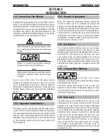
Throughout this manual, the word WARNING, CAUTION
and NOTE may appear. Pay particular attention to the
information provided under these headings. These special
annotations are easily recognized as follows:
!
WARNING
Gives information regarding possible personal
injury. Warnings will be enclosed in a box such
as this.
!
CAUTION
Refers to possible equipment damage.
Cautions will be shown in bold type.
NOTE
Offers helpful information concerning certain
operating procedures. Notes will be shown
in italics
You will also notice icons from the safety section
appearing throughout the manual. These are to advise
you of specific types of hazards or cautions related to
the portion of information that follows. Some may have
multiple hazards that apply and would look something
like this:
2.02 Equipment Identification
The Power Source's identification number (specification
or part number), model, and serial number usually appear
on a nameplate attached to the machine. Equipment which
does not have a nameplate attached to the machine is
identified only by the specification or part number printed
on the shipping container. Record these numbers for
future reference.
2.03 Receipt of Equipment
When you receive the equipment, check it against the
invoice to make sure it is complete and inspect the
equipment for possible damage due to shipping. If there is
any damage, notify the carrier immediately to file a claim.
Furnish complete information concerning damage claims
or shipping errors to the location in your area listed in the
inside back cover of this manual. Include all equipment
identification numbers as described above along with a
full description of the parts in error.
2.04 Description
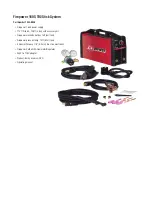
This compact inverter welding machine has infinitely
adjustable welding current from 10 to 160 amps. It uses
standard general purpose STICK (SMAW) 3/32” (2.5mm)
electrodes for light gauge work, generally less than
1/8” (3.2mm) thick and STICK (SMAW) 1/8” (3.2mm)
electrodes for heavier material. The unit also has a LIFT
TIG (GTAW) welding mode that offers stable TIG welding
characteristics when used with a suitable TIG torch and
shielding gas.
2.05 Transportation Methods
!
Disconnect input power
conductors from de-energized supply line before moving
the welding Power Source.
Lift Power Source with handle on top of case. Use
handcart or similar device of adequate capacity. If using
a fork lift vehicle, secure the Power Source on a proper
skid before transporting.
2.06 Duty Cycle
The rated duty cycle of a Welding Power Source, is the
percentage of a ten minute time period that it may be
operated at its rated output current without exceeding
the temperature limits of the insulation of the component
parts. To explain the 10 minute duty cycle period, suppose
a Welding Power Source is designed to operate with
a 30% duty cycle at 160 amperes and 26.4 volts. This
means that it has been designed and built to provide the
rated amperage (160A) for 3 minutes, i.e. arc welding
time, out of every 10 minute period (30% of 10 minutes
is 3 minutes). During the other 7 minutes of the 10
minute period the Welding Power Source must idle and
be allowed to cool.

