FireClass Prescient III Скачать руководство пользователя страница 47

FIRECLASS Prescient III 

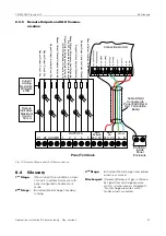
6.3 Commissioning Procedure

Application, Installation & Commissioning  Doc. version 2

47

The appropriate yellow alarm fault LED on the 
control board illuminates

The 

Algemeen Storing LED

 pulses

The internal buzzer pulses

The fault output operates

Replace the EOL resistor & check that the panel 
returns to quiescent.

15 Check that the alarm circuits are monitoring the wir-

ing for short circuits correctly. Place a wire link 
across the EOL resistor in the last device on the cir-
cuit and check that after a few seconds:

The 

Signaalgevers; Storing/Uit LED

 on 

the Display pulses.

The appropriate yellow alarm fault LED on the 
control board illuminates.

The 

Algemeen Storing LED

 pulses.

The internal buzzer pulses.

The fault output operates.

Remove the link & check that the panel returns to 
quiescent.

16 Repeat Steps 13 to 15 for alarm circuit 2 and the 

extinguishing alarm circuit.

17 Ensure that the Actuators are disconnected from the 

circuit cabling and are replaced with a suitable load 
as described above.

18 Remove the end of line device from the Actuator Cir-

cuit 1 terminals in the panel and connect the field 
cabling. After a few seconds observe that the panel 
returns to the quiescent condition.

19 Repeat open circuit & short circuit tests on actuator 

circuit 1 and check that the control panel reacts as 
follows:

The 

Blussturing Storing & Algemeen 

Storing LEDs 

pulse

The appropriate Actuator Fault LED on the control 
board illuminates

The internal buzzer pulses

The fault output operates

20 Repeat Steps 18 and 19 on Actuator circuit 2.

21 Any additional monitored circuits being used should 

also be connected in turn and checked for correct 
open/short circuit fault monitoring by removing or 
short-circuiting the EOL resistor on each circuit and 
checking that the correct fault indication is given on 
the panel.

Fault indications should clear once the EOL resistor 
is returned to normal.

22 Check that the 

HANDBEDIENING LED

 is illuminated. 

If not, press the 

AUTO & HAND / ALLEEN HAND


button once so that the 

HANDBEDIENING LED

 illu-

minates

23 Place zones 1 & 2 into the One-Man-Test mode as 

follows:

– Press the 

SELECTEER AAN/UIT

 button. The 

SELECT cursor should flash on the 

DOORMELD-

ING BRAND

 fault LED.

– Press the 

SELECT 

button. The cursor should 

move to the 

Groep 1

 fault LED.

– Press the 

TEST 

button. The 

Groep 1

 & 

Groep 

2

 fault LEDs should illuminate steady (with a cur-

sor flash on 

Groep 1

 fault LED). The 

TEST LED


should also illuminate steady.

– Press the 

SELECTEER AAN/UIT

 button to switch 

off the flashing cursor, leaving the 

Groep 1

 & 

Groep 2

 fault LEDs and the TEST LED illumi-

nated steady.

24 Activate the first detector on zone 1 and check that 

the control panel reacts as follows:

The red 

Groep 1

 Fire LED illuminates steady

Sounder circuits 1 & 2 operate

The internal buzzer in the control panel sounds

After four seconds the panel should automatically 
reset, resetting the detector and energising the 
RESET relay for 10 seconds.

25 Repeat step 24 above for all detectors on zone 1.

26 Repeat Steps  24 and 25


for zone 2, checking that the 

red Groep 2 Fire LED illuminates steady instead of 
the Zone 1 Fire LED.

27 Return zones 1 & 2 to normal as follows:

Press the 

SELECTEER AAN/UIT 

button. The 

SELECT 

cursor should flash on the 

DOORMELD-

ING BRAND

 fault LED.

Press the 

SELECT

 button. The cursor should 

move to the 

Groep 1

 fault LED.

Press the 

INSCHAKELEN

 button. The 

Groep 1

 & 

Groep 2

 fault LEDs should clear (with a cursor 

flash on 

Groep 1

 fault LED). The TEST LED 

should also clear.

Press the 

SELECTEER AAN/UIT

 button to switch 

off the flashing cursor.

28 Place the Auxiliary Zone into the One-Man-Test 

mode (using the 

SELECT

 cursor as for zones 1 & 2). 

Activate each detector & call point in turn and check 
that the panel responds as in 24 above (except that 
the 

EXTERNE GROEP

 Fire LED operates instead of 

the 

GROEP 1

 Fire LED).

29 Return the Auxiliary Zone to normal operation.

30 Operate the panel mounted Manual Release Point 

and check that the panel reacts as follows:

The red 

Handactivering LED

 pulses.

The red 

Systeem Aktief LED

 illuminates 

steady.

The 

EXTINGUISHING SOUNDER

 circuit operates

Actuator circuits 1 & 2 operate.

The internal buzzer in the control panel sounds. 

31 Activate the Pressure Switch input (if fitted) and 

check that the panel reacts as follows:

Содержание Prescient III

Страница 1: ...Application Installation Commissioning 120 515 161_FC P PRESCIENT3 I NL Doc version 2 24 February 2014 Conventional Fire Detection Gas Extinguishing Control Panel FIRECLASS Prescient III...

Страница 2: ...re reserved in particular but not limited to the rights of copying distribution and translation No portion of this documentation including the online help may be reproduced edited copied or distribute...

Страница 3: ...3 9 5 Extinguishing Isolation Valve Status ISO VALVE 16 3 9 6 Gas Released Pressure Switch GAS REL 16 3 9 7 Emergency Hold HOLD 16 3 9 8 Emergency Abort Input ABORT 17 3 10 Relay Contacts 17 3 10 1 F...

Страница 4: ...RING UIT MANUAL RELEASE FAULT DISABLED 25 3 18 15 BLUSSING UIT EXTINGUISHING DISABLED 25 3 18 16 DOORM BLUSSING STORING UIT GAS RELEASED SIGNAL DISABLED 25 3 18 17 ALGEMENE STURINGEN SHUTDOWN OUTPUTS...

Страница 5: ...ility 36 6 Panel Installation Commissioning 43 6 1 Cable Recommendations 44 6 2 Installation Procedure 44 6 3 Commissioning Procedure 45 7 System Maintenance 49 7 1 Overview 49 7 2 Weekly Test Routine...

Страница 6: ...6 Application Installation Commissioning Doc version 2 Contents FIRECLASS Prescient III...

Страница 7: ...guide is aimed at technicians who have to install a FIRECLASS Prescient III Fire detection system They should already have been given training Keyword Symbol Explanation DANGER Warning Imminent dange...

Страница 8: ...device 5 k Separate monitoring of the status of non electrical disable device s Isolation valve 6 n Input from auto manual selector switches 7 o Transmission of a triggering signal to equipment withi...

Страница 9: ...Sound alarms Silence Alarms Reset 10 Fully Monitored Outputs Configurable for Volt Free operation for First Stage Shutdown Second Stage Shutdown Third Stage Shutdown Auxiliary Fire Signal Auxiliary F...

Страница 10: ...STORING LAGE DRUK GASCILLINDERS HOGE DRUK VERZAMELLEIDING AFSLUITER ONJUIST AFSLUITER DICHT HANDACTIVERING STORING UIT BLUSSING UIT DOORM BLUSSING STORING UIT ALGEMENE STURINGEN UIT BLUSVER TRAGING SI...

Страница 11: ...on Status Input Isolation Valve Status 10K Abnormal 2K2 Open 680R Closed Status Input Gas Low 10K EOL 680R Gas Low DIL SW configurable for Normally closed operation Status Input Gas Released Pressure...

Страница 12: ...uiescent 0V when activated Actuator Circuit 1 1 2V in quiescent 24V when activated 3 8V in quiescent 0V when activated Extinguishing Sounder Circuit 1 2V in quiescent 24V when activated 3 8V in quiesc...

Страница 13: ...ntact Rated 1 Amp 24VDC Operating de energising on any fault including Valve Abnormal but not Valve Closed Operating on Gas P S active I P or Actuator operated when in No Discharge P S mode Open colle...

Страница 14: ...et 2 A Manual Release Call Point is mounted on the door of the panel and is monitored by a separate circuit for open short circuit faults The connection for the call point is on the rear of the displa...

Страница 15: ...used 24 V DC 2 AUX 1 A 24 V 0 V This output is rated at 1 A elec tronically fused 24 V DC 3 8 Status Lamp Unit The panel communicates with the Status Lamp Units SLU via two wire RS485 serial data The...

Страница 16: ...1 Valve Closed Activated by a 680 resistor flashing the Valve Closed LED on the display board pulsing the internal buzzer 2 Valve Open Activated by a 2 2 resistor no indication is given on the panel...

Страница 17: ...board In the Volt free mode clean contacts for Pole Normally Open Normally Closed are available rated at 1 A 30 V DC 3 10 2 Second Stage Shutdown 2ND STAGE The Second Stage Shutdown Relay is energised...

Страница 18: ...s the DOORM STORING STORING UIT LED on the display In the Volt free mode clean contacts for Pole Normally Open Normally Closed are available rated at 1 A 30 V DC 3 10 7 Auxiliary Reset RESET The Auxil...

Страница 19: ...Test Mode will operate the appropriate zonal fire indicator and the general sounder circuits for four seconds Switch ON A fire alarm on any zone in Test Mode will operate the appropriate zonal fire i...

Страница 20: ...l without a series end of line resistor RESET INHIBIT PERIOD Five switches allow the Extinguishing System Reset Inhibit timer to be configured from 0 to 30 minutes in 1 minute increments Any of the fi...

Страница 21: ...LEDs are mounted on the control board to indicate the following faults SHUTDOWN 3 FAULT Illuminates for an open or short circuit fault on the 3rd Stage monitored Out put SHUTDOWN 2 FAULT Illuminates f...

Страница 22: ...fault on the Gas Low input GAS RELEASED FLT Illuminates for any open or short cir cuit fault on the Gas Released input SLU FAULT Illuminates for a fault on any Status Lamp Unit CONFIG ON Illuminates w...

Страница 23: ...ff pulsing if a fire condition is detected on the aux zone illuminating steady when the alarm is accepted by operation of the Silence Alarms button The yellow LED is normally off pulsing for an open o...

Страница 24: ...Stage illuminating steady during the activated condition 2nd Stage The LED remains illuminated until the Extinguishing System is reset 3 18 5 BLUSSING AKTIEF GAS RELEASED This is a red LED that is nor...

Страница 25: ...steady when the Actuators are disabled Note When the actuators are disabled the Extinguishing Sounder circuit is automatically disabled 3 18 16DOORM BLUSSING STORING UIT GAS RELEASED SIGNAL DISABLED...

Страница 26: ...f the button can re enable a previously disabled cir cuit set a zone for intrinsically safe operation or move the cursor between SLU number and SLU type code digits See section 4 2 for details 3 19 9...

Страница 27: ...t is selected by moving the Circuit Select Cursor and then pressing INSCHAKELEN UITSCHAKELEN or TEST as required The process is as follows 1 Press the SELECTEER AAN UIT button The Select Cursor will a...

Страница 28: ...mp Units If SLUs are used with the panel the panel needs to know the type of SLU connected and the address of the SLU The configuration process is as follows 1 Move the CONFIG SLU DIL switch on the co...

Страница 29: ...ounded if necessary and the fire condition can be reset by operation of the HERSTEL BRANDALARM button 4 5 2 AUTOMATIC MANUAL MODE If a fire condition is detected on either zone 1 or zone 2 while the p...

Страница 30: ...y The Extinguishing System Reset Inhibit timer starts and the GEBLOKKEERD LED illuminates if config ured to a non zero value The Extinguishing Sounder circuit pulses 1 second ON 1 second OFF The Extin...

Страница 31: ...failed 160 mA 20 mA to 50 mA for each zone in alarm Ancillary equipment cur rent Alarm circuit current Solenoid circuit current Mains Failed current 60 mA Ancillary equip ment current Integral charger...

Страница 32: ...s to allow for deterioration of the batteries during use So the minimum battery capac ity required in this example is 1 25 x 3 83 4 79 Ah 5 2 2 Battery Replacement The useful life of the standby batte...

Страница 33: ...ox Incoming Mains Cable Secured with a cable tie Internally Wired Mains Cable 5A Power Supply Unit Mounted on Chassis Earth Lead to Earth Bar Earth Wire to Chassis Ambient Temperature Charger Set volt...

Страница 34: ...ed by a 5 A fuse Table 9 Mains Input Specification Panel Integrated Power Supply Output Specification Parameter Value Maximum Short Term Current Output I max b 4 8 A Maximum Continuous Current I max a...

Страница 35: ...m HT 100 mm Battery circuit protection F6 15AL250V 20 mm fast blow glass fuse Mains failed fault battery current 60 mA Ancillary equipment current Mains failed alarm battery current 160 mA 20 mA to 50...

Страница 36: ...Series 65 ionisation detector 32 55000 317 Series 65 Optical detector 32 55000 122 Series 65 heat detector A1R 32 55000 125 Series 65 heat detector BR 32 55000 132 Series 65 heat detector CR 32 55000...

Страница 37: ...l detector with SensAlert FasTest DirtAlert Flashing LED 32 ORB OH 13001 APO Orbis multi sensor detector with SensAlert FasTest DirtAlert 32 ORB OH 13003 APO Orbis multi sensor detector with SensAlert...

Страница 38: ...ET Linear Smoke Beam Detector 5 SLR E IS Photoelectric Intrinsically Safe Detector 25 DCD 1E IS Rate of Rise intrinsically Safe Detector incorporating a 60 deg fixed tempera ture element 25 YBN R 4 I...

Страница 39: ...fixed temperature 32 NHD G3 4T Grade 3 fixed temperature 32 NHD G H1 4T Range 1 fixed temperature detector 32 2kH 4T Photo electric 32 2IC 4T Ionisation detector 32 RB4 Mounting base System Sensor 11...

Страница 40: ...ed H600 Fixed Temperature heat detector 32 H601 Fixed Temperature heat detector 32 H602 Fixed Temperature heat detector 32 H604 Fixed Temperature heat detector 32 H900 Fixed Temperature heat detector...

Страница 41: ...and heat detector IS 24 MF601EX Ionisation detector IS 24 THORN S111 I R flame detector IS 12 S112 I R flame detector IS 12 S121 I R flame detector IS 12 S131 I R flame detector IS 12 S161 I R flame...

Страница 42: ...d on the use of a 22 uF capacitor as the end of line device except for intrinsically safe devices in which case the EOL is a 10 k resistor If the DIL switch option 3 9 k EOL is selected then the maxim...

Страница 43: ...er systems or any other radio transmit ting equipment The operating temperature range is 5 C to 40 C maximum humidity is 95 IMPORTANT SAFETY CONSIDERATIONS FOR BATTERIES WARNING Installation Complianc...

Страница 44: ...s 1 8 k brown grey red gold Reset 560 green blue brown gold Valve monitoring resistors Valve open 2 2 k red red red gold Valve closed 680 blue grey brown gold 3 off End of Line Capacitors 22 F Spare 2...

Страница 45: ...sistor across the terminals of the last device for any additional monitored input or output circuits being used 16 Place the chassis in the bottom of the enclosure and Re connect the internal mains ca...

Страница 46: ...opriate yellow Groep fault LED pulses The Algemeen Storing LED pulses The internal buzzer pulses The fault output operates Re connect the detector and check that the panel returns to quiescent 8 Repea...

Страница 47: ...BEDIENING LED illu minates 23 Place zones 1 2 into the One Man Test mode as follows Press the SELECTEER AAN UIT button The SELECT cursor should flash on the DOORMELD ING BRAND fault LED Press the SELE...

Страница 48: ...nnected to the Manual Release input The primary functions of the panel have now been tested The Panel can now be configured for the specific requirements of the site via the internal DIL switches Once...

Страница 49: ...all indications operate for 5 seconds and the buzzer sounds 6 Test one hold one abort and one auto manual switch if fitted These should be on separate SLUs and should be varied each week 7 Check that...

Страница 50: ...50 Application Installation Commissioning Doc version 2 7 3 Battery Replacement FIRECLASS Prescient III...

Страница 51: ...yout Diagram Fig 7 Control Board Layout Diagram yco Configuration Switch 1 Configuration Switch 2 Display Ribbon Connector Microcontroller Programming Header Manufacturer s Use Only Fault Status LEDs...

Страница 52: ...loded View Fig 8 Panel Exploded View 6 7 211 725 2 66 0 0 18 5 6 6 7 02817 1 187 2 1 2685 225 0 1 21752 2 5 0 18 5 6 211 725 66 6 57 225 57 66 6 57 5 6 7 6 7 5 21 66 0 1 2 3 4 5 6 7 8 386 3 7 0 18 5 6...

Страница 53: ...COM Detector Bases with optional Schottky Diode Zone2 wired identically to Zone1 End Of Line Capacitor 22uF 35V IN OUT COM Detector Base with optional Schottky Diode IN OUT IN OUT Manual Call Point w...

Страница 54: ...VOLT C1565 Polarity Suppression Board One per circuit Actuator Solenoid Coil Resistance 30R to6K ACT2 wired identically to ACT1 NOTE 3K9 End Of Line resistor is already fitted to the C 1565board This...

Страница 55: ...may be required to accommodate monitoring resistors 680 R W Normally Open Pressure Switch 10 K W EOL 680 R W Normally Open or Normally Closed Low Pressure Switch 10 K W EOL 2K2 W Valve Open 680R W Val...

Страница 56: ...as Gas Released Output 1 st Stage Shutdown Output Normally de energised 10k EOL These Outputs are Reverse polarity monitored at 5 VDC They are Active at 28 VDC Nominal Each Output can be configured i...

Страница 57: ...Communication Panel Terminals Z1 Z2 AUX MR 1 2 3 4 5 OUTPUTS 24V 0V AUX 250mA A B S L U 24V 0V AUX 1A 24V IN 0V IN 24V OUT 0V OUT RS485 A IN RS485 B IN RS485 A OUT RS485 B OUT Earth Bar inside Panel...

Страница 58: ...trol and delay device Environmental class A 1 flooding zone CO2 high pressure CO2 low pressure inert gas Halocarbon Provided options x Extinguishing system delay x Reception of a signal representing t...

Страница 59: ...FIRECLASS Prescient III 8 5 Construction Products Regulation Application Installation Commissioning Doc version 2 59...

Страница 60: ...ndustriale S Scolastica 64013 Corropoli TE Italy FireclassSales tycoint com www fireclass co uk United Kingdom FIRECLASS Hillcrest Business Park Cinder Bank Dudley West Midlands DY2 9AP United Kingdom...

Отзывы: