


18
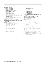
Application, Installation & Commissioning Doc. version 2
3.11 Internal Standby Batteries
FIRECLASS Prescient III
3.10.4 Gas Discharged (GAS REL SIG)
The Gas Discharged Relay is energised when the Gas
Released Pressure Switch input is activated, or when
the actuator circuits are operated if the panel is config-
ured for NO PRESSURE SWITCH.
A triple jumper link allows the output to be powered and
monitored (Link ON) or Volt-Free (Link OFF).
In the Monitored mode, an open or short circuit fault on
the field wiring illuminates the
Blussturing Stor-
ing LED
on the display and the Gas Released signal
Fault LED on the motherboard.
In the Volt-free mode, clean contacts for Pole, Normally
Open & Normally Closed are available, rated at 1 A,
30 V DC.
3.10.5 Fire Signal (FIRE SIG)
The Fire Signal Relay is energised when zones 1, 2 or
Aux zone detect a fire condition.
A triple jumper link allows the output to be powered and
monitored (Link ON) or Volt-Free (Link OFF).
In the Monitored mode, an open or short circuit fault on
the field wiring illuminates the Fire Signal Fault LED on
the display.
In the Volt-free mode, clean contacts for Pole, Normally
Open & Normally Closed are available, rated at 1 A,
30 V DC.
3.10.6 Fault Signal (FAULT SIG)
The Fault Signal Relay is a fail-safe relay and is normally
energised. It is de-energised for any fault condition on
the panel.
A triple jumper link allows the output to be powered and
monitored (Link ON) or Volt-Free (Link OFF).
In the Monitored mode, an open or short circuit fault on
the field wiring illuminates the DOORM. STORING;
STORING/UIT LED on the display.
In the Volt-free mode, clean contacts for Pole, Normally
Open & Normally Closed are available, rated at 1 A,
30 V DC.
3.10.7 Auxiliary Reset (RESET)
The Auxiliary Reset Relay is a single pole change-over
relay and is energised briefly when the panel is in Fire
Reset mode. The relay is energised for 10 seconds. This
is to allow ancillary equipment such as Beam Detectors
to be reset. The relay has no powered and monitored
mode and only volt-free contacts for Pole, Normally
Open & Normally Closed are available, rated at 1 A,
30 V DC.
3.11 Internal Standby Batteries
Terminals are provided to allow connection of one set of
internal standby batteries. The Charger Circuit is moni-
tored for the following:
Battery or associated wiring disconnected.
Battery fuse blown
Low battery voltage (<15.7 V ±0.4 V)
Battery and interconnection resistance is 0.35 Ω or
higher.
3.12 Function Enable/Disable
Switches
Two sets of DIL switches and one jumper link are avail-
able on the motherboard to allow the panel to be config-
ured for additional site-specific functions:
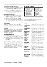
3.12.1 Function Select Switch
This consists of two sets of 12-way DIL switches, pro-
viding the following options:
1
23
4
5
ON
CONFIG I/S INPUTS
PRE-DISCHARGE DELAY 5S
PRE-DISCHARGE DELAY 10S
SW1
78
9
10
11
12
6
PRE-DISCHARGE DELAY 20S
PRE-DISCHARGE DELAY 40S
SILENT ZONE TEST
BUZZER DISABLE
LATCHED FAULTS
INSTANT MANUAL RELEASE
BUZZER PULSES AT END OF DELAY
ZONES 1 & 2 SINGLE KNOCK
NO DISCHARGE PRESSURE SWITCH
1
23
4
5
ON
ACTUATOR S/C DISABLE
1 MIN
2 MIN
SW2
78
9
10
11
12
6
4 MIN
8 MIN
16 MIN
CLEAR ACTUATORS AFTER 1 MIN
SILENCE ALARMS BEFORE RESET
OUTPUT 1-AUTO, 2-MANUAL
CONFIG SLU
3K9 EOL
N/C GAS LOW I/P
RESET
INHIBIT
PERIOD


