


20
Application, Installation & Commissioning Doc. version 2
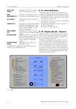
3.12 Function Enable/Disable Switches
FIRECLASS Prescient III
INSTANT MANUAL RELEASE
Switch OFF:- Operation of Manual Release starts
the Pre-discharge delay timer.
Switch ON:- Operation of Manual Release bypasses
the Pre-discharge delay timer & operates the actua-
tor circuits immediately.
BUZZER PULSES AT END OF DELAY
Switch OFF:- No change in the state of the internal
buzzer during the last five seconds of the Pre-dis-
charge delay timer.
Switch ON:- The internal buzzer pulses during the
last five seconds of the Pre-discharge delay timer.
ZONES 1 & 2 SINGLE KNOCK
Switch OFF:- If the system is set to Auto & Manual
mode, a fire condition on both zones 1 & 2 is
required to start the pre-discharge delay timer.
Switch ON:- If the system is set to Auto & Manual
mode, a fire condition on either zone 1 or zone 2 will
start the pre-discharge delay timer.
NO DISCHARGE PRESSURE SWITCH
Switch OFF:- The Panel only indicates BLUSSING
AKTIEF when the GAS REL. input is activated (via a
Discharge Pressure switch).
Switch ON:- The panel indicates BLUSSING AKTIEF
as soon as the actuator circuits are activated.
ACTUATOR S/C DISABLE
Switch OFF:- The actuator circuits are monitored for
open & short circuit faults.
Switch ON:- The actuator circuits are only monitored
for open circuit faults. Used for open-circuit fault
monitoring of the solenoid coil without a series end-
of-line resistor.
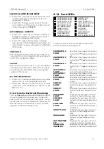
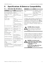
RESET INHIBIT PERIOD
Five switches allow the Extinguishing System Reset
Inhibit timer to be configured from 0 to 30 minutes in 1-
minute increments. Any of the five switches in the ON
position adds to the timer value, up to a maximum of 30
minutes.
CLEAR ACTUATORS AFTER 1 MIN
Switch OFF:- The actuator circuits are energised
until the Extinguishing System is reset.
Switch ON:- The actuator circuits are only energised
for 1 minute and then are de-energised.
Reset
Inhibit
Length
(minutes)
SW2-2
1m
SW2-3
2m
SW2-4
4m
SW2-5
8m
SW2-5
16m
0
OFF
OFF
OFF
OFF
OFF
1
ON
OFF
OFF
OFF
OFF
2
OFF
ON
OFF
OFF
OFF
3
ON
ON
OFF
OFF
OFF
4
OFF
OFF
ON
OFF
OFF
5
ON
OFF
ON
OFF
OFF
6
OFF
ON
ON
OFF
OFF
7
ON
ON
ON
OFF
OFF
8
OFF
OFF
OFF
ON
OFF
9
ON
OFF
OFF
ON
OFF
10
OFF
ON
OFF
ON
OFF
11
ON
ON
OFF
ON
OFF
12
OFF
OFF
ON
ON
OFF
13
ON
OFF
ON
ON
OFF
14
OFF
ON
ON
ON
OFF
15
ON
ON
ON
ON
OFF
16
OFF
OFF
OFF
OFF
ON
17
ON
OFF
OFF
OFF
ON
18
OFF
ON
OFF
OFF
ON
19
ON
ON
OFF
OFF
ON
20
OFF
OFF
ON
OFF
ON
21
ON
OFF
ON
OFF
ON
22
OFF
ON
ON
OFF
ON
23
ON
ON
ON
OFF
ON
24
OFF
OFF
OFF
ON
ON
25
ON
OFF
OFF
ON
ON
26
OFF
ON
OFF
ON
ON
27
ON
ON
OFF
ON
ON
28
OFF
OFF
ON
ON
ON
29
ON
OFF
ON
ON
ON
30
OFF
ON
ON
ON
ON
31
ON
ON
ON
ON
ON
Table 4: Instant Manual Release
Note
This facility is only to be used where the actu-
ators connected to the actuator circuits
remain activated when the power is removed
and require manual resetting. This facility is
not intended to control the gas discharge
period. It is only provided as a means to
reduce current consumption during gas dis-
charge.


