


FIRECLASS Prescient III
3.5 Actuator Circuits (ACT1 & ACT2)
Application, Installation & Commissioning Doc. version 2
15
3.5
Actuator Circuits (ACT1 &
ACT2)
Two fully monitored actuator circuits are provided. They
are monitored for Open Circuit and Short Circuit faults
(short circuit fault indication can be disabled). They are
rated at 1 A (fused), 28 V DC each. The End-Of-Line
device is a 10 kΩ resistor (3.9 kΩ can also be used).
The
Blussturing Storing LED
on the display
flashes for any fault condition on either Actuator Circuit,
with individual fault LEDs on the motherboard inside the
panel. Both circuits can be disabled by disabling the
extinguishing system (the Extinguishing Alarm circuit is
also disabled at the same time).
Note: The circuits are reverse-polarity monitored. The
PCB terminals are marked for the active polarity. Ensure
that all connected devices are polarised. See section
8.3.2.
3.6
Repeater Outputs (Z1, Z2,
AUX, MR, OUTPUTS 1, 2,
3, 4, 5)
Each repeater output consists of an Open Collector tran-
sistor driver capable of sinking up to 50 mA. The follow-
ing outputs are provided:
Z1 - Zone 1 Fire
Z2 - Zone 2 Fire
AUX - Auxiliary Zone Fire
MR - Manual Release Activated
OUTPUT 1 - Emergency Hold Activated (configur-
able for auto & manual mode)
OUTPUT 2 - Emergency Abort Activated (configur-
able for manual only mode)
OUTPUT 3 -System Disabled
OUTPUT 4 - Isolation Valve Closed
OUTPUT 5 - Isolation Valve Abnormal
3.7
Auxiliary 24 V DC Supply
The panel provides two auxiliary d.c. power supply out-
puts for connection to ancillary equipment:
1
AUX 250 mA: 24 V, 0 V) - This output is rated at
250 mA (electronically fused), 24 V DC.
2
AUX 1 A: 24 V, 0 V) - This output is rated at 1 A (elec-
tronically fused), 24 V DC.
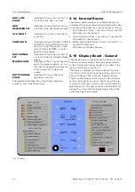
3.8
Status Lamp Unit
The panel communicates with the Status Lamp Units
(SLU) via two-wire RS485 serial data. The following indi-
cations can be provided, dependent on SLU type:
1
BLUSSING GEBLOKKEERD
2
UITSTEL BLUSSING
3
BLUSSING AKTIEF
4
Auto & HANDBEDIENING
5
HANDBEDIENING
6
BLUSSING UIT
7
SLU STORING
8
BLUSVERTRAGING (fully functional SLU only)
The SLU can provide the following controls, dependent
on SLU type:
1
HANDACTIVERING
2
BLOKKEER
3
UITSTEL
4
AUTOMATISCH & HANDBEDIENING / HANDBEDI-
ENING
The controls on the SLU can be transmitted via the
serial data link or hard-wired via conventional circuits on
the panel.
3.9
Remote Inputs
3.9.1
Remote Controls
This is a fully monitored input, providing: open & short
circuit fault monitoring, Silence Alarms, Re-sound
Alarms and Panel Reset. The EOL device is a 10kΩ
resistor.
Remote Sound Alarms:
Non-latching.
4.7 kΩ = activate general sounders.
When activated - steady "Remote Sound Alarms"
indication and continuous operation of general
sounders.
When deactivated - "Remote Sound Alarms" indica-
tion clears and general sounders stop.
Remote Silence Alarms:
Single Operation.
1.8 kΩ = silence active sounders (silencing of extin-
guishing sounders is inhibited until the Discharged
condition is active)
When activated - same operation as pressing the
Silence Alarms button.
When deactivated - no action
Remote Reset:
Single Operation.
560 Ω = Reset Fire System & Extinguishing System
(reset of the extinguishing system can be inhibited
until the inhibit timer ends or Abort is operated)
When activated - Resets all indications on the Fire
Alarm section of the panel. Only resets indications
on the Extinguishing section of the panel if the Reset
Inhibit is inactive.
When deactivated - no action