


46
Application, Installation & Commissioning Doc. version 2
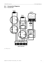
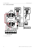
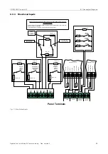
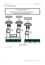
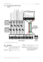
6.3 Commissioning Procedure
FIRECLASS Prescient III
– The green
IN BEDRIJF LED
illuminates (display)
– The yellow
Handbediening
LED
illuminates
(display).
– The yellow
Algemeen Storing LED
flashes
(display).
– The yellow
Voeding Storing LED
flashes (dis-
play).
– The yellow
Batt/Charge Fault LED
is illumi-
nated (control board).
– The internal buzzer sounds (control board).
– The Auxiliary Fault Relay operates.
No other indications should be present at this time,
if there are, identify the fault and rectify it by check-
ing the following:
– That no field wiring is connected.
– That the EOL devices are connected correctly in
the panel terminals on each monitored circuit.
2
Connect the batteries to the control board observing
correct polarity. Observe (after 20 to 30 seconds)
that the control panel reacts as follows:
The buzzer silences and the fault indications
extinguish.
The IN
BEDRIJF LED
remains lit.
The System
AUTOMATISCH
&
HANDBEDIENING
LED remains lit.
Locate the Thermistor in free air space directly
above the batteries. Use a tie wrap to secure the
Thermistor to one of the battery leads.
3
Press the Test button on the display board and check
that the control panel reacts as follows:
All LEDs on the display board and the control
board illuminate for 5 seconds.
The internal buzzer sounds for 5 seconds.
4
Switch off the mains AC supply to the control panel
and check that the control panel reacts as follows:
The
Algemeen Storing LED
on the display
board pulses.
The
Voeding Storing LED
on the display
board pulses.
The internal buzzer in the control board sounds.
The Fault Relay operates.
The Mains Fault LED on the control board
illuminates.
5
Restore the mains supply to the panel.
6
Remove the end of line device from the zone 1
terminals in the panel and connect the field cabling.
After a few seconds observe that the panel returns
to the quiescent condition.
7
For each detector on zone 1, remove the detector
from it’s base and check that after a few seconds:
The appropriate yellow Groep fault LED pulses
The
Algemeen Storing LED
pulses
The internal buzzer pulses
The fault output operates
Re-connect the detector and check that the panel
returns to quiescent.
8
Repeat Step 6 and 7 on zone 2 and the auxiliary
zone.
9
Check that the zone detection circuits are monitor-
ing the wiring for short circuits correctly. For each
zone in turn, place a wire link across the end of line
device and check that after a few seconds:
The appropriate yellow Groep fault LED pulses
The
Algemeen Storing LED
pulses
The internal buzzer pulses
The fault output operates
Remove the link and check that the panel returns to
quiescent.
10 Remove the end of line device from the Manual
Release Zone terminals in the panel and connect the
field cabling. After a few seconds observe that the
panel returns to the quiescent condition.
11 Check that the Manual Release Zone circuit is mon-
itoring the wiring for open circuits correctly by dis-
connecting the End-Of-Line resistor at the end of the
circuit and checking that after a few seconds:
The yellow
Handactivering; Storing/Uit
LED
pulses.
The
Algemeen Storing LED
pulses.
The internal
FIELD MR FAULT LED
illuminates
steady.
The internal buzzer pulses.
The fault output operates.
Re-connect the EOL resistor and check that the
panel returns to quiescent.
12 Check that the Manual Release Zone circuit is mon-
itoring the wiring for short circuits correctly by plac-
ing a wire link across the Manual Release zone end
of line device and checking that after a few seconds:
The yellow
Handactivering; Storing/Uit
LED
pulses
The
Algemeen Storing LED
pulses
The internal
FIELD MR FAULT LED
illuminates
steady
The internal buzzer pulses
The fault output operates
Remove the link and check that the panel returns to
quiescent.
13 Remove the end of line device from the Alarm
Circuit 1 terminals in the panel and connect the field
cabling. After a few seconds observe that the panel
returns to the quiescent condition.
14 Check that the alarm circuit is monitoring the wiring
for open circuits correctly. Remove the EOL resistor
from the last device on the circuit and check that
after a few seconds:
The
Signaalgevers; Storing/Uit LED
for
on the Display pulses


