6
Commissioning
30
Festo – SBRD-EN – 2017-11 – English
6.4
Connection to higher-order controller
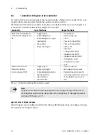
For control of the device or processing of the inspection results, a higher-order controller (PLC) can be
connected to the camera system through the available connection options.
The following I/O functions are available, depending on the device and firmware used. Assignment to
a connection or interface is done during configuration of the job:
Connection
Input functions
Output functions
Device internal, digital I/O
module at the plugs X2, X3,
X4
–
Trigger signal
–
Acknowledge error
–
Acknowledge error, apply
input signal
–
Job number
–
Apply input signal
–
Not assigned
–
Ready to operate
–
Errors
–
Pass on the input X2.2
–
Pass on the input X2.3
–
Always off
–
Always on
–
Configuration mode
–
Inspection result OK
–
Inspection result not OK
–
Orientation correct
–
Orientation incorrect
–
Type
Communication over
Ethernet interface
(protocol-based I/O)
–
Trigger signal
–
Apply input signal
–
Acknowledge signal error
–
Job preselection
–
Job parameter
–
Job tolerances
–
Ready to operate
–
Warning and error status
–
Detailed inspection results
with recognised parts type and
characteristics as values or
text
Tab. 6.2
Connection options of the camera system
Note
A higher-order controller must be programmed according to the signal behaviour of
the selected evaluation mode. Here, observe the descriptions of the signal processes
starting with Chapter 6.3.1 ff.
Logical status of inputs/outputs
Some I/O signals can be configured with the CCS software
è
Job Navigator step 6 Configure I/O, selec
tion Digital inputs or Digital outputs.


