6
Commissioning
Festo – SBRD-EN – 2017-11 – English
33
Note
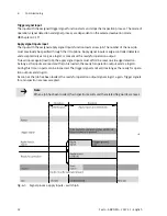
Simplified representation. The signal processes contain no jitter, run times or system-
related delays.
Note
The inputs must be validly present for a certain time, depending on the I/O options
used.
Acknowledge error signal input
If an error state occurs, this is displayed at the error status output with a logic 1. In addition, the ready
for operation output goes to logic 0.
Incoming trigger signals are not valid, that is, no further evaluations are possible until the error is elim
inated.
The error must be eliminated through suitable means, while the system remains in an error status.
Diagnostics and changing of job parameters are still possible.
Use the CSS software or all protocols that can access job parameters.
As soon as the error has been eliminated, this must be reported to the camera system through
the input with the related acknowledge signal error function. The acknowledge error signal is edge-
controlled detected.
Information on the errors (description and recommendations for elimination) is in Chapter 7.1.2.
6.4.2
Use of the Ethernet interface with Telnet
The device provides the Telnet protocol for communication with a higher-order controller, robot, or PC.
This allows very comprehensive output and control options. Inspection results can be processed fur
ther in the higher-order controller, for example, to grasp a part with a robot.
Support of the Telnet function by the camera system must be activated through job parameters. Read
ing and writing are performed through a text-based command line with defined commands, where
the data to be read/written are defined by memory addresses.
Besides simple commands for image recording, among other things, the device also makes available
access to the results of an inspection and the settings of the job parameters.
Specific memory addresses can be read and written, while some can only be read or written
è
Tables in the appendix A.3.


