


12 / 20
Festo 7Tension01_TBb_en
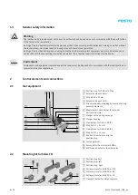
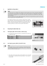
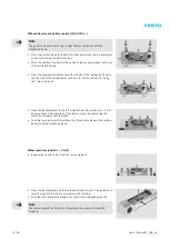
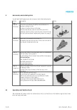
With position stops and distance pieces (ELGA-TB-G-…)
Note
The position stops are necessary to align the test equipment with the
toothed belt axis.
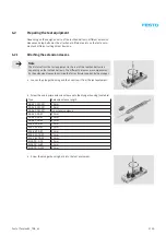
•
Place the position stops for the ELGA toothed belt axis on the test equipment
and secure it using the knurled screws.
•
Place the position stop bolts in the position stops as appropriate to the size
of the toothed belt axis.
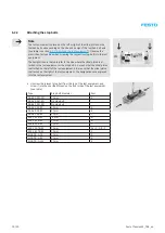
•
Place the appropriate distance piece for the size of the toothed belt axis on
the free side of the test equipment and secure it at the position “E” using
the 7 mm ø stop bolt.
•
Place the test equipment to the left or right of the
slide/piston (S.L. or S.R.)
as appropriate to the position of the distance piece (must be facing the
slide) in accordance with the table.
•
Push the test equipment forwards so that the position stops on the cylinder
barrel touch the toothed belt axis.
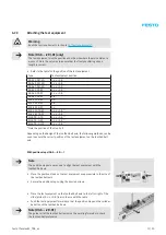
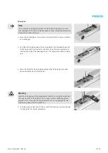
Without position stops (EGC-…-TB-KF)
•
Remove the position stops from the test equipment.
•
Place the test equipment on the toothed belt axis in front of the guide rail to
the left or right of the slide in accordance with the table.
•
Push the test equipment backwards so that it is touching the guide rail.
Note
The test equipment is attached to the guide rail by means of integrated
magnets.
Содержание DGE-25 ZR RF Series
Страница 1: ...Repair instructions en Toothed belt axis DGE 25 ZR KF DGE 40 ZR KF DGE 63 ZR KF 7DGE_25 63_ZR_KFb_en...
Страница 47: ......
Страница 48: ......
Страница 49: ...Operating instructions en Toothed belt pretension test equipment 7Tension01_TBb_en...


