
21 / 48
Festo 7DGE_25-63_ZR_KFb_en
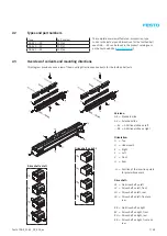
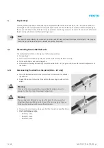
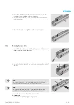
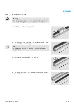
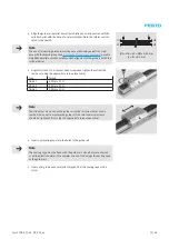
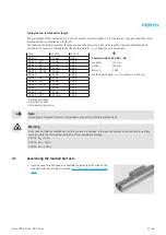
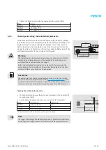
Setting the linear guide
The roller bearing cartridge pairs must be set using the threaded pins so that
the displacement resistance for the slide is as low as possible and it can move
without backlash. The setting is made in pairs.
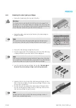
The following description must be repeated in succession for both roller
bearing cartridge pairs.
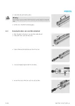
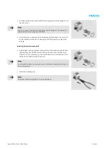
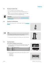
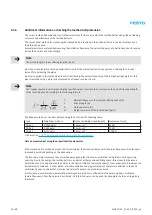
• Apply Loctite 243 to the three new threaded pins and screw these into the
previously recut tapped holes of the roller bearing cartridge pair to be set.
Note
The tapped holes must be recut before the new threaded pins are screwed
in. Residues from the old locking agent in the tapped holes result in uneven
and increased torques for the threaded pins, which means it is more difficult
to feel what is happening when setting the roller bearing cartridge pairs.
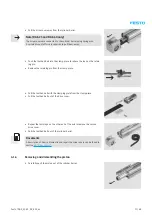
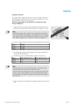
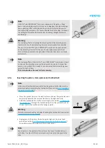
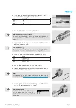
• Pretension the three threaded pins using the appropriate torque (see table).
Type
Torque
DGE-25
10 Ncm
DGE-40
10 Ncm
DGE-63
10 Ncm
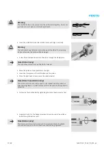
• Check the guide backlash and the displacement resistance (see table) by
moving the slide several times.
• The slide must move smoothly and without jerking on the guide rail.
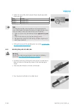
Type
Min. displacement force
Max. displacement force
DGE-25
1 N
5 N
DGE-40
1 N
5 N
DGE-63
2 N
8 N
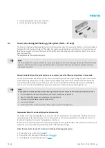
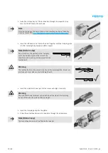
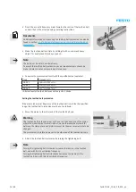
Note
The displacement force can be determined using an electronic hand-held
force measuring device (pressure and tensile force meter).
In general, the mechanical awareness of the user is important when setting
the linear guide. Poor operating behaviour manifests itself through operat-
ing noise. Excessive pretensioning manifests itself through harsh, increased
operating noise.
• Adjust the setting of the threaded pins until the operating behaviour is flaw-
less.
Содержание DGE-25 ZR RF Series
Страница 1: ...Repair instructions en Toothed belt axis DGE 25 ZR KF DGE 40 ZR KF DGE 63 ZR KF 7DGE_25 63_ZR_KFb_en...
Страница 47: ......
Страница 48: ......
Страница 49: ...Operating instructions en Toothed belt pretension test equipment 7Tension01_TBb_en...


