Protective func-
tions
Description
Measures required during installa-
tion and commissioning
Electronic current
limiting and I²t mon-
itoring of the motor
current
The motor current is
monitored electronically
and limited in accordance
with the limit values
specified in the standard
è
EN 61800-5-1, Tab. 29.
Motor currents and I²t time
constant can be parameter-
ised.
–
Parameterise the nominal current, max-
imum current and I²t time constant of the
motor, e.g. using the device-specific plug-
in.
Thermal memory in
the event of motor
switch-off
supported, cannot be para-
meterised
–
none
Thermal memory in
the event of a power
supply failure
Speed-sensitive over-
load protection
supported from firmware
version V019, parameteris-
able
–
Parameterise I²t monitoring with speed-
dependent scaling, e.g. with the device-
specific plug-in.
Such as for:
–
Synchronous servo motors (lower permis-
sible current at high rotational speed)
–
Fan motors (lower permissible current at
low rotational speed)
Tab. 35: Protective functions for the motor
The specified parameters are preset for Festo motors. The parameters can be
adapted in the plug-in.
7.9.4
Shield support of the motor cable
Requirements for the motor cable shield support on the device side
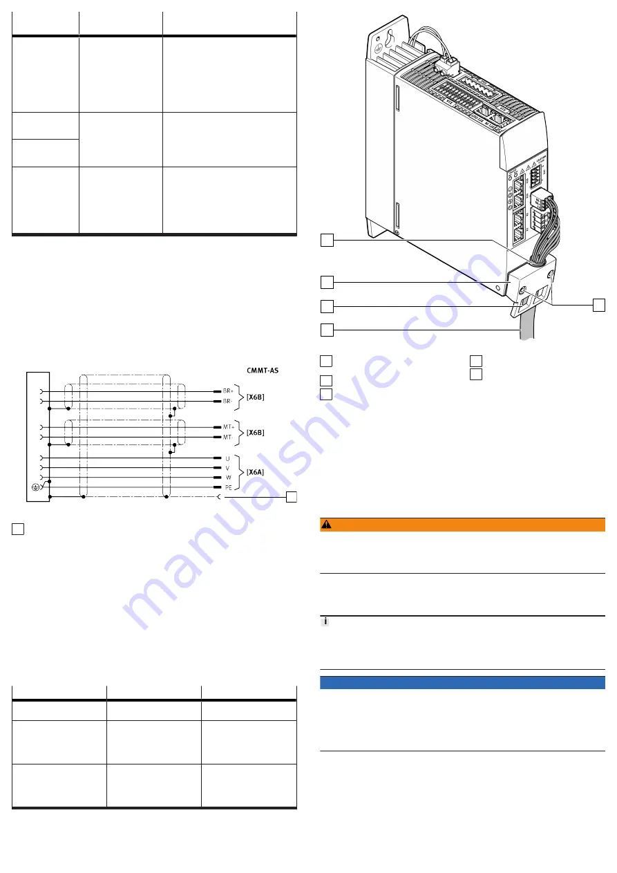
The type of shield support depends on the design of the motor cable. If,
for example, a hybrid cable is used to connect the motor, holding brake and
temperature sensor, the following options are available for connecting the shield
on the device side:
Option 1: all motor cable shields are jointly connected over a wide surface area
using a shield sleeve at the cable end and are connected below the shield clamp
on the front of the CMMT-AS.
1
Fig. 9: Shared shield support of all cable shields (example)
1 Shield sleeve
Option 2: the outside shield of the motor cable is connected separately over a
wide surface area below the shield clamp on the front of the CMMT-AS. The inside
shields are connected separately to the designated FE pin of the connection [X6B].
•
Make unshielded cable ends as short as possible.
Mounting the shield clamp
The lower section of the front panel of the housing is used as a shield support
surface. The shield support surface, together with the shield clamp, allows the
motor cable shield to be connected over a wide surface area.
1. Using the shield clamp, press the motor cable shield or the conducting
shield end sleeve of the motor cable onto the shield support surface of the
housing
2. Tighten the retaining screws (2x) of the shield clamp with a size T20 TORX
screwdriver. Pay attention to the clamping range and observe the tightening
torque specified below.
Property
Value
Comments
Clamping range
11 mm … 15 mm
Diameter of the stripped cable
or shield sleeve
Tightening torque for the
retaining screws in the case of
block mounting
1.8 Nm ± 15%
In the case of block mounting,
the shield clamp makes full
contact with the base of
the housing (cable diameter
11 mm)
Minimum tightening torque
with larger cable diameter
(
>
11 mm … 15 mm)
0.5 Nm ± 15%
With a higher tightening
torque, make sure that the
connecting cable does not get
crushed in the clamping area
due to excessive pressure.
Tab. 36: Tightening torque and clamping range
1
2
3
4
5
Fig. 10: Shield clamp of the motor cable
1 Retaining screws of the shield
clamp
2 Motor cable
3 Cut-out for mounting cable
binders (2x)
4 Shield clamp
5 Motor cable shield connected
over a large surface area below
the shield clamp
Motor cable shield support on the motor side
Detailed information on the motor-side connection with motor cables from Festo
è
Assembly instructions for the motor cable
•
Connect all shields to the PE over a wide surface area on the motor side,
e.g. via the shield connection provided on the motor connector or the shield
support surface in the motor junction box.
7.10
Power and logic voltage supply
7.10.1
[X9A], power supply and DC link circuit connection
Supply of the control unit (logic voltage supply)
WARNING
Risk of injury due to electric shock.
• For the electrical power supply with extra-low voltages, use only PELV circuits
that guarantee a reinforced isolation from the mains network.
• Observe IEC 60204-1/EN 60204-1.
•
Only connect PELV circuits with an output current of max. 25 A. Otherwise,
use a separate external fuse: 25 A.
Power supply and DC link circuit connection
The connections for the logic voltage supply, the power voltage supply and the
link circuit are not protected against wiring errors. The reversal of the connections
results in a device defect during switch-on.
With cross-wiring, observe the polarity of the DC link connection on all devices.
NOTICE
Overvoltage due to asymmetrical mains load
If the neutral conductor has to be disconnected when the device is switched
on and off, the device can be damaged by overvoltage due to an asymmetrical
network load.
• Design the mains connection with fuse and main switch so that the neutral
conductor is always switched on early and switched off later.


