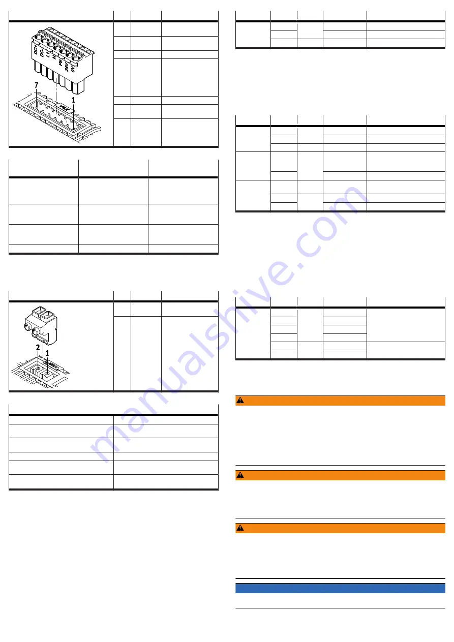
[X9A]
Pin
Function
Description
7
DC+
DC link circuit positive
potential
6
DC-
DC link circuit negative
potential
5
L1
Mains supply phase L1
4
N
For 1-phase mains con-
nection: mains supply
neutral conductor
For 2-phase mains con-
nection: mains supply
phase L2
3
PE
Protective earthing
2
24 V
Positive potential of the
24 V logic voltage
1
0 V
Reference potential of
the 24 V logic voltage
Tab. 37: Power supply and DC link circuit connection
Requirements for the
connecting cable
Single device
Device compound
Number of insulated wires and
shielding
5 insulated wires, unshielded
Without DC link coupling:
5 wires, unshielded
With DC link coupling: 7 wires,
unshielded
Min. conductor cross section
including wire end sleeve with
plastic sleeve
0.5 mm
2
1 mm
2
Max. conductor cross section
including wire end sleeve with
plastic sleeve
2.5 mm
2
2.5 mm
2
Max. length
2 m
£
0.5 m
Tab. 38: Requirements for the connecting cable
7.10.2
[X9B], connection for braking resistor
The connection [X9B] is located on the top of the device. The internal braking
resistor or a suitable external braking resistor is attached to the connection [X9B].
[X9B]
Pin
Function
Description
2
BR+Ch
Braking resistor positive
connection
1
BR-Ch
Braking resistor negative
connection
Tab. 39: Connection for the braking resistor
Requirements for the connecting cables of external braking resistors
Number of insulated wires and shielding
2 wires, shielded
Min. conductor cross section incl. wire end
sleeve with plastic sleeve
0.25 mm
2
Max. conductor cross section incl. plastic wire
end sleeve
2.5 mm
2
Max. cable length
2 m
Wiring
inside the control cabinet, shield connected to
PE
Tightening torque of the screw terminals on the
mating plug GIC 2.5 HCV/2-ST-7.62
0.5 … 0.6 Nm
1)
1) Specification of the manufacturer at the time the documentation was approved
Tab. 40: Requirements for the connecting cable
Selection of suitable braking resistors
Information on selecting suitable braking resistors
è
Manual Assembly, Installa-
tion.
7.11
Cross-wiring
Cross-wiring makes it possible to set up a device compound consisting of up to 10
servo drives CMMT-AS. The different cross-wiring options are as follows:
–
Cross-wiring of I/O signals at the connection [X1A]
–
Cross-wiring of the mains and logic voltage supply without DC link coupling
–
Cross-wiring of the mains and logic voltage supply with DC link coupling
Information on cross-wiring
è
Manual Assembly, Installation and Manual Safety
sub-function.
7.12
STO installation
Inputs and outputs for the safety sub-function STO
The 2-channel request for the safety sub-function is made via the digital inputs
#STO-A and #STO-B. The STA diagnostic output indicates whether the safe status
has been reached for the safety sub-function STO.
Connection Pin
Type
Identifier
Function
[X1A]
X1A.11
DIN
#STO-B
Safe torque off, channel B
X1A.12
#STO-A
Safe torque off, channel A
X1A.22
DOUT
STA
Safe torque off acknowledge
Tab. 41: Inputs and outputs for the safety sub-function STO
7.13
SBC installation
Inputs and outputs for the safety sub-function SBC
The 2-channel request for the safety sub-function is made via the digital inputs
#SBC-A and #SBC-B at the connection [X1A]. The SBA diagnostic output indicates
whether the safe status has been reached for the safety sub-function SBC. The
holding brake is connected via the connection [X6B]. The external clamping unit is
connected via the connection [X1C].
Connection Pin
Type
Identifier
Function
[X1A]
X1A.9
DIN
#SBC-B
Safe brake control, channel B
X1A.10
#SBC-A
Safe brake control, channel A
X1A.21
DOUT
SBA
Safe brake control acknowledge
[X1C]
X1C.1
DOUT
BR-EXT
Output for connection of an
external clamping unit (high-side
switch)
X1C.5
GND
Reference potential (ground)
[X6B]
X6B.1
–
FE
Functional earth connected to pro-
tective earth
X6B.2
OUT
BR+
Holding brake (positive potential)
X6B.3
BR–
Holding brake (negative potential)
Tab. 42: Inputs and outputs for the SBC safety sub-function
7.14
SS1 installation
Inputs and outputs for the safety sub-function SS1
The safety sub-function SS1 is wired like the safety sub-function STO but is
supplemented by the functional input CTRL-EN so that the braking ramp can be
activated by the safety relay unit.
7.15
Installation for operation without safety sub-function
Minimum wiring for operation without safety sub-function
For operation without the safety sub-function, wire inputs X1A.9 to X1A.12 as
follows:
Connection Pin
Type
Identifier
Function
[X1A]
X1A.9
DIN
#SBC-B
Supplies each one with 24 V
X1A.10
#SBC-A
X1A.11
#STO-B
X1A.12
#STO-A
X1A.21
DOUT
SBA
Do not connect
X1A.22
STA
Tab. 43: Wiring of inputs and outputs without safety sub-function
8
Commissioning
8.1
Safety
WARNING
Risk of injury from electric shock in the event of incomplete insulation at the
power connections [X6A], [X9A] and [X9B].
Before operating, plugging in or unplugging the operator unit CDSB or a con-
nector from a hot-plug-capable interface, the following points must be fulfilled:
• The conducting lines at the device are completely insulated.
• The protective earthing (PE) and the shield connection are correctly connected
to the device.
• The housing is free of damage.
WARNING
Severe, irreversible injuries from accidental movements of the connected
actuator technology.
Unintentional movements of the connected actuator technology can result from
exchanging the connecting cables of a servo drive or between servo drives.
• Before commissioning: All cables must be correctly assigned and connected.
WARNING
Risk of injury from electric shock.
Contact with live parts at the power connections [X6A], [X9A] and [X9B] can result
in severe injuries or death.
• Do not pull out power supply plugs while live.
• Before touching, wait at least 5 minutes after switching off the load voltage to
allow the intermediate circuit to discharge.
NOTICE
During commissioning: Keep the range of movement of the connected actuators
clear, so that no persons are endangered.


