1
2
3
4
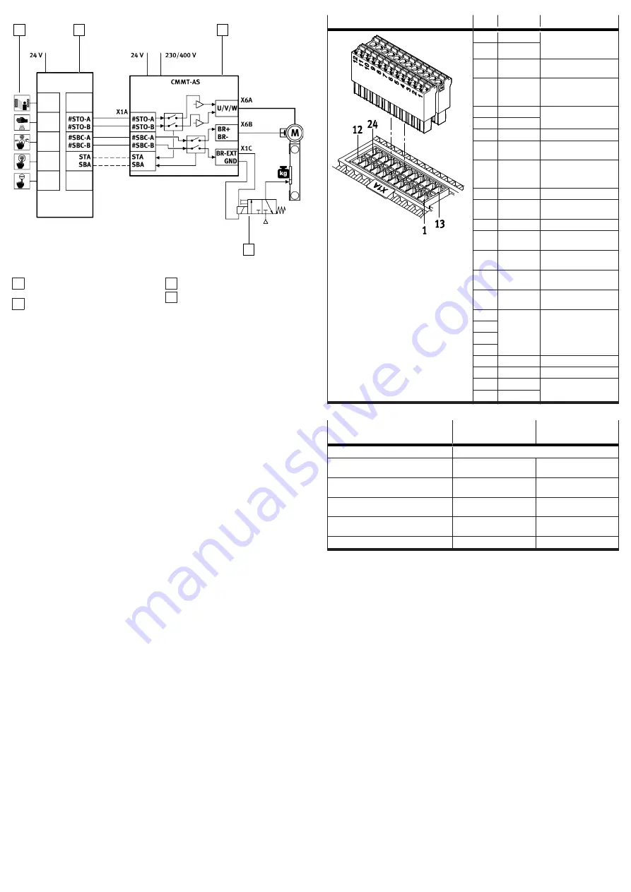
Fig. 8: SBC sample circuit
1 Input device for safety request
(e.g. light curtain)
2 Safety relay unit
3 Servo drive CMMT-AS
4 Control (here solenoid valve
example) of the clamping unit
Information on the sample circuit
The safety request is passed on to the servo drive on 2 channels via the inputs
#SBC-A and #SBC-B at the connection [X1A].
–
The request via the input #SBC-A switches off power to the signals BR+ and BR-
at the connection [X6B]. This de-energises and closes the holding brake.
–
The request via the input #SBC-B switches off power to the signal BR-EXT at the
connection [X1C]. This shuts off power to the control of the external clamping
unit. The clamping unit closes.
–
The safety relay unit monitors the SBA diagnostic output and checks whether
the safe status has been reached for the safety sub-function SBC.
7.8
Interfaces
Observe the requirements for mating plugs
è
Manual Assembly, Installation.
7.8.1
[X1A], inputs and outputs for the higher-order PLC
The I/O interface [X1A] is located on the top of the device. This interface offers
access to functional and safety-related inputs and outputs of the device. These
include, for example:
–
Digital inputs for 24 V level (PNP logic)
–
Digital outputs for 24 V level (PNP logic)
–
Signal contact for safety chain (RDY-C1, RDY-C2)
–
Differential analogue input ±10 V control voltage
The inputs and outputs of this I/O interface are used for coupling to a higher-
order PLC. The safety-related inputs and outputs are connected to a safety relay
unit.
[X1A]
Pin
Function
Description
24
RDY-C1
Normally open contact:
ready for operation mes-
sage (Ready)
23
RDY-C2
22
STA
Diagnostic output Safe
torque off acknowledge
21
SBA
Diagnostic output Safe
brake control acknowl-
edge
20
–
reserved, do not connect
19
–
18
SIN4
Release brake request
17
GND
Reference potential
(ground)
16
TRG0
fast output for triggering
external components,
channel 0
15
TRG1
like TRG0, but channel 1
14
CAP0
fast input for position
detection, channel 0
13
CAP1
like CAP0, but channel 1
12
#STO-A
Control input Safe torque
off, channel A
11
#STO-B
Control input Safe torque
off, channel B
10
#SBC-A
Control input Safe brake
control, channel A
9
#SBC-B
Control input Safe brake
control, channel B
8
–
reserved, do not connect
7
6
5
4
ERR-RST
Error acknowledgement
3
CTRL-EN
Power stage enable
2
AIN0
Differential analogue
input
1
#AIN0
Tab. 16: Inputs and outputs for the higher-order PLC with the CMMT-AS-...-S1
Requirements for the connecting
cable
Single device
Device compound
Shielding
Unshielded
Min. conductor cross section incl.
wire end sleeve with plastic sleeve
0.25 mm
2
–
Max. conductor cross section incl. plastic
wire end sleeve
0.75 mm
2
–
Min. conductor cross section incl. double
wire end sleeve with plastic sleeve
–
0.25 mm
2
Max. conductor cross section incl. double
wire end sleeve with plastic sleeve
–
0.5 mm
2
Max. length
3 m
0.5 m
Tab. 17: Requirements for the connecting cable
7.8.2
[X1C], inputs and outputs for the axis
The I/O interface [X1C] is located on the front of the device. This interface makes
functional and safety-related inputs and outputs available for components on the
axis. Output BR-EXT is used in conjunction with the safety sub-function Safe brake
control
è
Manual Safety sub-function.


