8
EN
Never attempt to remove the guard.
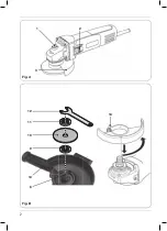
Mounting and removing the wheel disc
(Fig. B)
• Always use suitable wheel disc for this
machine with diameter Ø 100 / 115 / 125 mm
and a bore from 16 / 22 / 22 mm the thickness
of the wheel disc should be 6 mm for wheel
disc for grinding and 3 mm for wheel disc
for cutting, the mounting wheel disc may not
touch the safety guard.
Mounting
• Place the machine on a table with the
protection guard (3) facing upwards.
• Mount the flange (9) onto the spindle (8).
• Place the wheel disc (10) onto the spindle (8).
• Keep the spindle lock button (1) pressed and
firmly tighten the clamping nut (11) onto the
spindle (8) by using the spanner (12).
Removing
• Place the machine on a table with the
protection guard (3) facing upwards.
• Keep the spindle lock button (1) pressed and
loosen the clamping nut (11) using the spanner
(12).
• Remove the wheel disc (10) from the spindle (8).
• Keep the spindle lock button (1) pressed and
firmly tighten the clamping nut (11) using the
spanner (12).
3. OPERATING
Make sure that the work piece is properly
supported or fixed and keep the supply
cord routing away from the work area.
Switching on and off (Fig. A)
• To switch the machine on, press the On/off
switch (2).
• To switch the machine off, release the On/off
switch (2).
Hold the machine away from the work piece when
turning it on and off because the wheel disc could
damage the work piece.
• Clamp the work piece firmly or use another
method to ensure that it cannot move while
working.
• Check the discs regularly. Worn wheel discs
have a negative effect on the machine’s efficien-
cy. Change to a new wheel disc in good time.
• Always first turn the machine off after use
before removing the plug from the socket.
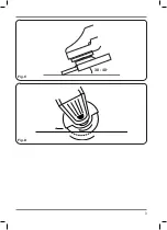
Deburring (Fig. C)
An angle of inclination of 30º to 40º will give the
best results when deburring. Move the machine
back and forth using light pressure. This will
prevent the work piece from discolouring or
becoming too hot and will avoid making groves.
Never use abrasive cutting discs for
deburring work!
Cutting (Fig. D)
For cutting, a special protection guard must be
used (not included).
Maintain firm contact with the work piece to
prevent vibration and do not tilt or apply pressure
and when cutting. Use moderate pressure when
working, appropriate to the material that is
being worked on. Do not slow down wheel discs
by applying sideways counter pressure. The
direction in which you want to cut is important.
The machine must always work against the
direction of the cut; so never move the machine
in the other direction! There is the risk that the
machine will catch in the cut causing kickback
and that you will lose control.
Hints for optimum use
• Clamp the work piece. Use a clamping device
for small work pieces.
• Hold the machine with both hands.
• Switch on the machine.
• Wait until the machine has reached full speed.
• Place the wheel disc on the work piece.
• Slowly move the machine along the work
piece, firmly pressing the wheel disc against
the work piece.
• Do not apply too much pressure on the
machine. Let the machine do the work.
• Switch off the machine and wait for the
machine to come to a complete standstill
before putting the machine down.
Содержание AGM1093P
Страница 2: ...2 Fig B Fig A 8 13 9 10 11 12 14 1 2 3...
Страница 3: ...30 40 o 3 Fig C Fig D...
Страница 132: ...132 BG AGM1093P 750W 100 AGM1094P 750W 115 AGM1095P 950W 125 Ferm Ferm 1 a b c...
Страница 133: ...133 BG d e f g h i j k l m n...
Страница 134: ...134 BG o p a b c d e a b c d...
Страница 135: ...135 BG e f a b c d e f II RCD RCD...
Страница 137: ...137 BG 6 3 3 9 8 10 8 1 11 8 12 3 1 11 12 10 8 1 11 12 3 2 2 C 30 40 D...
Страница 138: ...138 BG 4 3 BS 1363 7A N L 2012 19...
Страница 139: ...139 RU AGM1093P 750 100 AGM1094P 750 115 AGM1095P 950 125 FERM Ferm 1 a b...
Страница 140: ...140 RU c d e f g h i j k...
Страница 141: ...141 RU l m n o p a b c d e a b...
Страница 142: ...142 RU c d e f a b c d e f...
Страница 144: ...144 RU B 100 115 125 16 22 22 6 3 3 9 8 10 8 1 11 8 12 3 1 11 12 10 8 1 11 12 3 2 2 C 30 40 D...
Страница 145: ...145 RU 4 3 BS 1363 7A N L 2012 19 EC...
Страница 146: ...146 EL AGM1093P 750W 100mm AGM1094P 750W 115mm AGM1095P 950W 125mm Ferm Ferm 1...
Страница 147: ...147 EL...
Страница 148: ...148 EL...
Страница 149: ...149 EL II...
Страница 151: ...151 EL B 100mm 115mm 125mm 16 22 22 mm 6 mm 3 mm 3 9 8 10 8 1 11 8 12 3 1 11 12 10 8 1 11 12 3 A 2 On off 2 C 30 40 D...
Страница 152: ...152 EL 4 3 BS 1363 13A N L 2012 19 EU...
Страница 153: ...153 MK AGM1093P 750W 100mm AGM1094P 750W 115mm AGM1095P 950W 125mm FERM FERM 1...
Страница 154: ...154 MK a b c d max e f g 1 min h i j...
Страница 155: ...155 MK k l m n o p a b c d e a b c d...
Страница 156: ...156 MK e f a b c d j max e f II RCD RCD 2...
Страница 158: ...158 MK 11 12 10 8 1 11 12 3 A n ff 2 On Off 2 C 30 40 D 4 3 BS 1363 7A N L...
Страница 159: ...159 MK 2012 19 EU...
Страница 169: ...169 Exploded view AGM1095P...
Страница 170: ...170...
Страница 172: ...WWW FERM INDUSTRIAL COM 2021 FERM 2104 08...


