7
pletely before the blocking button is pressed. To fit the disc,
proceed as follows:
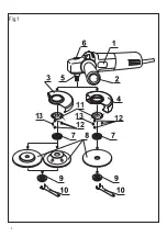
1. Block the spindle (shaft)
5
, by pressing the blocking
button
6
.
2. With the pin spanner
10
, remove the clamping nut
9
from the spindle
5
.
3. Fit the abrasive disc on the support plate
7
.
4. Replace the clamping nut
9
, using the pin spanner
10.
The position of the nut
9
will depend on the thickness of the
disc
5. Once the disc is fitted, check that the blocking button
has returned to its original position due to movement of the
incorporated spring.
STARTING THE TOOL
WARNING!
Check that the mains voltage is the same
as that in the machine’s specifications.
Plug the machine in with the switch off. Start the
machine by turning the switch to position 1 (“ON”). To
switch off, do the same in reverse.
WORKING INSTRUCTIONS
For cutting or deburring, the part to be worked on must
be secured, unless it is heavy enough to remain in a stable
position by itself.
For optimum performance and results when deburring,
it is advisable that the surface and the disc form an angle
of approximately 30º-40º. Guide the tool by pressing
lightly forwards and backwards. This prevents the part
from overheating or changing colour and the formation of
striations.
WARNING!
Never use a cutting disc for deburring.
When cutting, do not exert pressure on the disc. Do not
tilt the machine. The disc should not tilt or oscillate. Work
with a steady speed, appropriate for the type of material.
When cutting, bear in mind the direction of the work.
Guide the machine against the direction of the cutting tool,
never in the opposite direction; otherwise there is a risk
of the machine veering off the cutting line uncontrollably.
When cutting profiles or rectangular section tubes, we
recommend starting the cut on the shortest side.
NOISE AND VIBRATION
This tool has been designed and made to reduce
noise to a minimum. However, in spite of this,
in certain
circumstances the maximum noise level in the place of
work could exceed 85 dBA. In this case, the operator
should wear ear protection.
The machine’s noise and vibration levels, measured in
compliance with EN60745, usually reach:
AG115/1000
AG125/1000
Sound pressure level, dB(A)
88.83
91.1
Sound power level, dB(A)
99.8
102.1
Uncertainty K, dB(A)
3
3
Vibration total values a
h
, m/s
2
3.2
3.2
Uncertainty K, m/s
2
1.5
1.5
Use ear protection!
WARNING!
The vibration level given in these
instructions has been measured in accordance with
a standardized measurement procedure specified in
EN60745 and can be used to compare devices. Different
uses of the device give rise to different vibration levels and
in many cases they may exceed the values given in these
instructions. It is easy to underestimate the vibration load
if the electrical power tool is used regularly in particular
circumstances.
Note.
If you wish to make an accurate assessment of
the vibration loads experienced during a particular period of
working , you should also take into account the intervening
periods of time when the device is switched off or is running
but is not actually in use. This can result in a much lower
vibration load over the whole of the period of working.
ACCESSORIES
Accessories and their corresponding order number
can be found in our catalogues.
MAINTENANCE AND CARE
WARNING!
Always unplug the machine before
carrying out work on it.
- Inspect the tool: Using a worn deburring or cutting tool
will diminish the efficiency of the work and could damage
the motor.
- Inspect the mounting screws: Regularly inspect all the
mounting screws and ensure they are firmly tight-ened.
Should any screw be loose, tighten it immediately. Failure
to do so could put you at serious risk.
- Motor maintenance: Always take the greatest care
over this and make sure that the motor winding is not
damaged and does not become wet with oil or water.
- The vents should always be kept clean and free of
obstacles.
- Clean the machine thoroughly after each use. Blast
the motor regularly with compressed air.
- Check that the mains lead is in good condition. If it is
not, take it to an Official Service Centre to have it replaced.
- Brush replacement: The brushes should be replaced
after 150 - 200 hours use or when they are less than 10
mm long. Have this done by an Official Service Centre. We
recommend that at every second change of brushes, you
take the machine to one of our Official Service Centres for
general cleaning and oiling.
- Use only Felisatti accessories and spares. Parts the
changing of which is not covered in this instruction man-
ual, should be replaced in a Felisatti Official Service Centre
(See Warranty/Official Service Centre address leaflet).
WARRANTY
See general warranty conditions printed on the
attached sheet.
DISPOSAL
WARNING! Do not dispose of electric tools in the
household waste!
In accordance with European Directive 2002/96/EC
relating to old electrical and electronic appliances and
its translation into national law, used electric tools must
be collected separately and recycled in an ecologically
desirable way.
Содержание AG115/1000
Страница 2: ...AG115 1000 AG125 1000 WINKELSCHLEIFER...
Страница 3: ...2 Fig 1 11 12 13 12 13...
Страница 37: ...36 1 b 2 b d f 3 b d f g 4 b...
Страница 38: ...37 d f g 5 a b c d e f g 1 h i j k...
Страница 39: ...38 l m n o p a b c d e a b c d e a b c...
Страница 40: ...39 d e f a a a b...
Страница 43: ...42 4 12 13 11 11 180 13 2 2 3 6 S17 7 9 10 14 80 45 4 2 0 220 1 9 30 40...
Страница 44: ...43 85 AG115 1000 AG125 1000 88 83 91 1 99 8 102 1 3 3 2 3 2 3 2 2 1 5 1 5 Y 40 80 FELISATTI FELISATTI...
Страница 45: ......
Страница 46: ......
Страница 47: ......
Страница 48: ......


