3-phase servomotors. FXM
3-PHASE SERVOMOTORS. FXM
T
echni
cal data. T
or
qu
e-Spee
d curves
2.
Ref.2105
· 51 ·
FXM|FKM
SERVOMOTOR
2.9
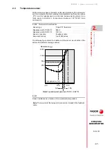
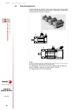
Technical data. Torque-Speed curves
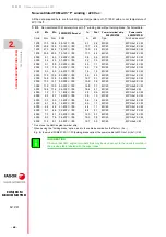
The following sections provide the main technical data of each model and
their torque-speed graphs for servomotors with A winding (400 Vac) and F
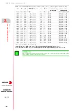
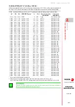
winding (220 Vac). Here are also the tables associating the servomotor
model with the FAGOR drives that can govern it. Bear in mind that
selecting the drive to govern a particular servomotor depends on the
requirements of the application; in other words, on the peak torque that
may be demanded from the servomotor for brief instants.
Hence, if the servomotor duty cycle in the application were the rated value
all the time, it would be enough to select a drive that can provide this
torque. However, applications with this kind of behavior are rare. In
general, there is always an instant that requires increasing the torque
beyond the rated value (e.g. for a rapid tool positioning in G00 when
machining) and, consequently, the peak torque must be higher than the
rated (nominal) torque.
Drive selection. General criterion
The tables shown later on provide the possible servomotor-drive
combinations. It has been assumed as
general criterion
to demand a
peak torque (Mp) that the drive must provide that is 2 or 3 times the stall
torque of the servomotor it is going to govern. See that this value is given
in the tables by the Mp/Mo ratio.
Observe that servomotor-drive combinations whose ratio is lower than 2
have been left out although, as mentioned earlier, there could be
applications that could use a smaller drive than the one shown in the
tables. Therefore, it is essential to know the requirements of the
application before selecting the drive. If they are unknown, we
recommend to apply the general criteria mentioned earlier.
It goes without saying that drives whose Mp/Mo ratio is higher than 3 can
also be selected; however, bear in mind that any oversizing (except in
very particular cases) makes the system unnecessarily more expensive.
Calculation of the drive peak torque
Observe that having the Mp/Mn ratio has required getting the peak torque
value of the drive (Mp). This value results from multiplying the peak
current (Ip) of the selected drive by the torque constant (Kt) of the
servomotor it is going to control. Remember that the values of the peak
c u r r e n t o f FA G O R d r i v e s a r e s h o w n i n s o m e t a b l e s i n t h e
“man_dds_hard.pdf” manual.
Limiting the drive peak torque
Observe if result of the previous calculation is a drive peak torque value
higher than the peak torque value of the servomotor it is going to govern,
this value will limit the other one. Therefore, the drive never provides a
peak torque higher than that of the servomotor. This fact appears in the
tables with values in bold characters.
When mentioning FAGOR drives throughout this document, we mean
AXD, ACD, MMC and CMC drives; i.e. drives for controlling synchronous
servomotors with A winding (powered at 400 Vac).
Remember that FAGOR also offers ACSD and MCS drives powered at
220 Vac (L series) and at 400 Vac (H series) that can also govern these
servomotors (with F and A winding respectively).
If you wish to control the motor with any of them, consult the selection
table for these drives shown on the first pages of its corresponding
manual. Observe that each drive family mentioned here has its own
manual.
Explanatory notes
Содержание FXM1 Series
Страница 1: ...MOTOR FXM FKM Installation manual Ref 2105...
Страница 34: ...1 GENERAL CONCEPTS General concepts 34 Ref 2105 FXM FKM SERVOMOTOR...
Страница 173: ......

