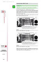
3-phase servomotors. FKM
3-
PHASE SERVOM
O
TORS. FKM
Co
nne
ctio
ns
3.
Ref.2105
· 115 ·
FXM|FKM
SERVOMOTOR
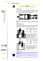
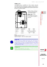
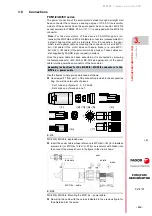
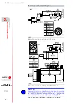
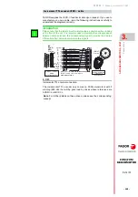
Extract piece 6 located inside piece 7 and insert each wire one by one
with its pin already crimped into the corresponding hole (it must be
inserted in the order shown in figure
with Nr. 12) all the way in.
Observe that each hole is numbered according to figure
Finally screw pieces 1 and 7. All the pins will be guided internally and
properly to their relevant output pins of the connector. All the pieces
will fall perfectly into place inside. Use the right tools to properly screw
both pieces.
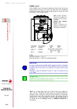
F- 3/14
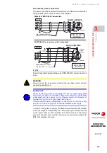
“SF-Z0026” tool from Phoenix Contact.
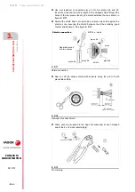
F- 3/15
Channeling the wires already crimped.
Note.
Make sure that the signal transmitted by each wire corresponds
with the hole numbered according to the table in figure
.
Note.
Observe that the crimped pins do not stick out once the cable has
been assembled to the connector.
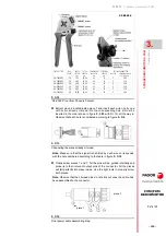
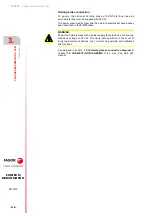
F- 3/16
Final power cable assembling step.
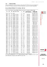
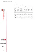
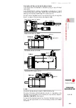
CONTACT TYPE
Ø mm
SOCKET
CROSS
SECTION
mm²
TOTAL
LENGTH
mm
CONDUCTOR
INSERT Ø
mm
STRIPPING
LENGTH
mm
SETTING PARAMETERS
LOCATOR
CRIMPING ARBOR
SETTING mm
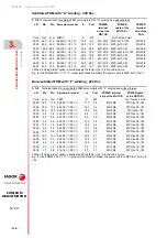
SM-36KS002
3.6
2.50
36.95
4.5
10
3
2.00
SM-36KS002
3.6
4.00
36.95
4.5
10
3
2.10
SM-36KS003
3.6
4.00
36.95
5.4
10
3
2.20
SM-36KS003
3.6
6.00
36.95
5.4
10
3
2.50
SM-36KS004
3.6
6.00
36.95
6.4
10
3
2.78
SM-36KS004
3.6
10.00
36.95
6.4
10
3
3.00
SF-Z0026
piece 7
piece 1
Содержание FXM1 Series
Страница 1: ...MOTOR FXM FKM Installation manual Ref 2105...
Страница 34: ...1 GENERAL CONCEPTS General concepts 34 Ref 2105 FXM FKM SERVOMOTOR...
Страница 173: ......

