Quick reference
25
(S
OFT
03.1
X
)
PROBING CANNED CYCLES (MILLING)
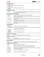
ISO coded cycles are defined with the #PROBE instruction followed by the number of the cycle to be executed
and the call parameters.
The optional parameters appear between angular brackets .
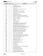
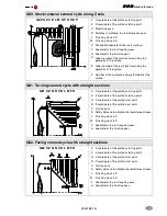
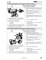
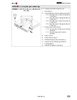
#PROBE 1. Tool calibration (dimensions and wear)
#PROBE 1 B <I> <J> F <K> <S> <N> <D> <L>
<M> <C> <X U Y V Z W>
J
Type of operation.
• "J"=0: Tool calibration.
• "J"=1: Tool wear measurement.
F
Probing feedrate.
K
Probe side to be used:
• "K"=0: Calibration on the X+ side.
• "K"=1: Calibration on the X- side.
• "K"=2: Calibration on the Y+ side.
• "K"=3: Calibration on the Y- side.
S
Speed and turning direction of the tool.
N
Number of edges to measure.
D
Distance from the probing point.
L
Maximum length wear allowed.
M
Maximum radius wear allowed.
B
Safety distance.
C
Behavior when exceeding the maximum wear:
I
Dimension of the tool to be calibrated:
• "C"=0: it shows a message of rejected tool and
stops the cycle.
• "C"=1: the cycle replaces the worn out tool with
another one of the same family.
• "I"=0: length, along the tool shaft.
• "I"=1: length, at one end of the tool.
• "I"=2: the radius.
• "I"=3: the tool radius and length.
X..W Tabletop probe position.
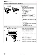
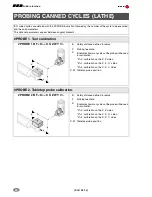
#PROBE 2. Probe calibration
#PROBE 2 X Y Z B J E H F
X..Z Theoretical coordinates of the arc center.
B
Safety distance.
J
Theoretical hole diameter.
E
Withdrawal distance after initial probing.
H
Feedrate for the initial probing movement.
F
Probing feedrate.
B
B
D
N
XY Z
B
E
B
J
Содержание CNC 8070
Страница 1: ...Quick reference SOFT 03 1X REF 0706 CNC 8070...
Страница 44: ......


