Operating manual
CNC 8055
CNC 8055i
O
PERATING
IN JO
G MODE
2.
·TC· O
PTION
S
OFT
: V02.2
X
·51·
Tool
con
tro
l
2.6.2
Variable tool change point
If the manufacturer so wishes, he can let the user define the tool change point every time. Obviously,
this feature depends on the type of machine and type of tool changer.
This feature may be used to change the tool next to the part, thus avoiding movements to a tool
change point located far away from it.
To do this:
• Define the text 47 of program 999997 so the CNC requests the X, Z coordinates of the tool
change point.
For example: ;47 $CHANGE POSITION
These coordinates must be referred to machine zero point, so the zero offsets do not affect the
tool change point. Therefore, the CNC can show, next to the X, Z coordinates and in small
characters, the coordinates of the axes referred to machine reference zero.
• Text 33 of program 999997 must be defined so the CNC shows the coordinates of the axes
referred to machine reference zero.
For example: ;33 $MACHINE ZERO
Since the operator can change the tool change point at any time, the subroutine associated with
the tools must consider those values. Arithmetic parameters P290 and P291 contain the values set
by the operator as tool change position in X and Z respectively.
In subroutine 55 of the previous section, the line setting the movement to the tool change point must
be modified:
Where it says:
G0 G53 XP??? ZP??? ; Movement to the tool change point.
It must say:
G0 G53 XP290 ZP291 ;User-defined movement to the change point.
Define the coordinates of the tool change point (X, Z)
1.
Press the [T] key to select the «T» field.
2.
Then press the [X], [Y] or [Z] key of the desired axis or the [
] [
] [
] [
] keys.
3.
After placing the cursor on the coordinates of the axis to be defined, define the desired values.
After placing the cursor on the coordinates of the axes to be defined, the value is entered in one
of the following ways.
• Entering the value manually. Key in the desired value and press [ENTER].
• Assign the current machine position.
Jog the axis with the handwheel or the JOG keys up to the desired point. Press [RECALL] so
the selected data assumes the value shown in the top right window and press [ENTER].
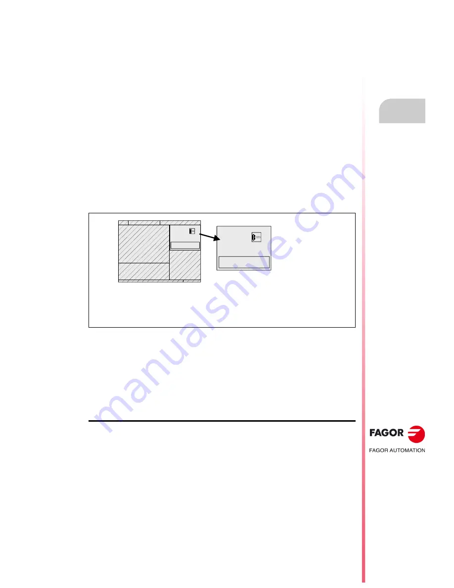
The top right window shows the tool position at all times.
Arithmetic parameter P290.
Change position in X.
Arithmetic parameter P291.
Change position in Z.
T 02
D 12
CHANGE POSITION
X 25.000 Z 85.000
S 150
T 02
D 12
CHANGE POSITION
X 25.000 Z 85.000
S 150
Содержание 8055 FL
Страница 1: ...CNC 8055 TC Operating manual Ref 1711 Soft V02 2x...
Страница 6: ...6 Operating manual CNC 8055 CNC 8055i SOFT V02 2X...
Страница 10: ...10 CNC 8055 CNC 8055i Declaration of conformity and Warranty conditions...
Страница 14: ...14 CNC 8055 CNC 8055i Version history...
Страница 20: ...20 CNC 8055 CNC 8055i Returning conditions...
Страница 22: ...22 CNC 8055 CNC 8055i Additional notes...
Страница 24: ...24 CNC 8055 CNC 8055i Fagor documentation...
Страница 32: ...32 Operating manual CNC 8055 CNC 8055i 1 GENERAL CONCEPTS TC OPTION SOFT V02 2X Managing the CYCLE START key...
Страница 74: ...74 Operating manual CNC 8055 CNC 8055i 2 OPERATING IN JOG MODE TC OPTION SOFT V02 2X ISO management...
Страница 180: ...180 Operating manual CNC 8055 CNC 8055i 4 Y AXIS TC OPTION SOFT V02 2X Tool calibration...
Страница 196: ...196 Operating manual CNC 8055 CNC 8055i 6 SAVING PROGRAMS TC OPTION SOFT V02 2X Managing programs using the explorer...
Страница 206: ...206 Operating manual CNC 8055 CNC 8055i 7 EXECUTION AND SIMULATION TC OPTION SOFT V02 2X Graphic representation...
Страница 207: ...Operating manual CNC 8055 CNC 8055i 7 SOFT V02 2X 207...
Страница 208: ...208 Operating manual CNC 8055 CNC 8055i 7 SOFT V02 2X...
Страница 209: ......


