background image


XTP T HWP 101 4K Wallplate Transmitter • Installation

15

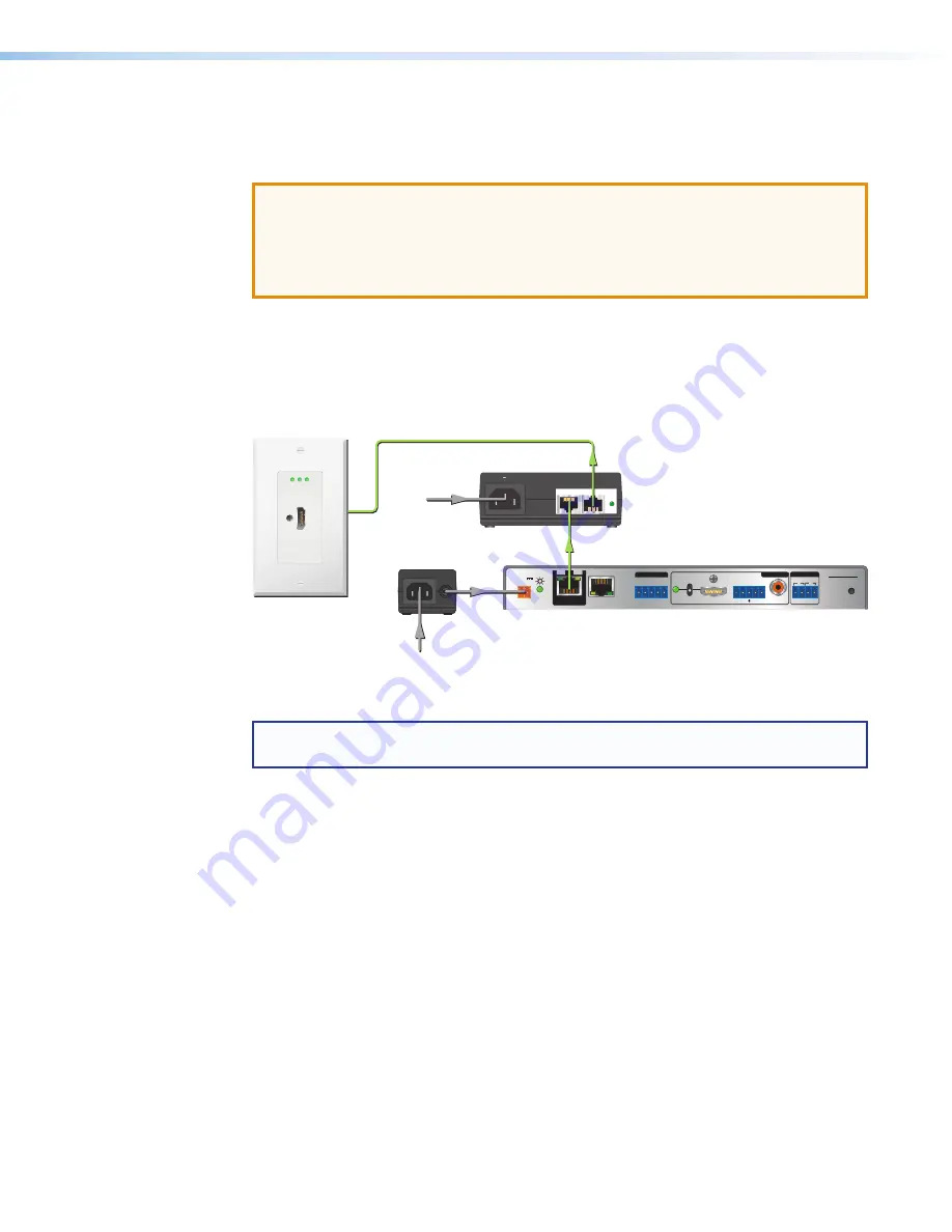
Remote power

The XTP T HWP 101 4K can be powered remotely through an XTP Power Injector or 
through an XTP matrix switcher.

ATTENTION:


• 

XTP remote power is intended for indoor use only. No part of the network that uses 
XTP remote power should be routed outdoors.

• 

XTP à distance est destiné à une utilisation en intérieur seulement. Aucune partie 
du réseau qui utilise l’alimentation XTP à distance ne peut être routée en extérieur.

Power injector

To power the XTP T HWP 101 4K remotely with an XTP Power Injector, power one 
device locally (see 

Local power

 on page 13) and connect an XTP power injector to 

the XTP cable run along the XTP connectors (see the 

XTP Power Injector User Guide

 at 

www.extron.com

 for more installation information).

Extron 

XTP T HWP 101 4K

XTP Transmitter

HDMI IN

PWR HDMI HDCP

Extron

HDMI IN

PWR HDMI HDCP

Extron

POWER

12V
         

0.7A MAX

Rx G

Tx

RS-232 

IR

XTP R HD 4K

R

L

Rx

Tx

-

+

-

+

-

+

1

2

AUDIO

ON

AUDIO

RESET

LAN

OVER  XTP

OUTPUTS

RELAYS

SIG              LINK

XTP IN

HDMI

OFF

S/PDIF

Extron 

XTP R HD 4K

XTP Receiver 

XTP

PWR

XTP PWR

100-240V 50/60 Hz

0.4A MAX

Extron 

XTP PI 100

XTP Power Injector

12V Local Power 

Supply

Power 

Shielded Twisted Pair 

Cable

Remote Power

Figure 12. 

Typical Pont-to-Point Application with Remote Power to an 
XTP T HWP 101 4K

NOTE:

  The power injector provides remote power up to 330 feet with a shielded twisted 

pair cable with 24 AWG wire.

XTP matrix switcher

XTP matrix switchers have a fixed amount of power available to provide remote power to 
connected XTP devices (see the XTP matrix switcher user guide at 

www.extron.com

 for 

more details). To manage available power from the XTP matrix switcher, use the XTP System 
Configuration Software with the XTP matrix switcher.

Содержание XTP T HWP 101 4K

Страница 1: ...User Guide XTP T HWP 101 4K XTP Systems XTP Transmitter Decorator Style Wallplate 68 2876 01 Rev C 01 19 ...

Страница 2: ...uninsulated dangerous voltage within the product s enclosure that may present a risk of electric shock ATTENTION This symbol when used on the product is intended to alert the user of important operating and maintenance servicing instructions in the literature provided with the equipment For information on safety guidelines regulatory compliances EMI EMF compatibility accessibility and related topi...

Страница 3: ... Display Sync Processing DMI Dynamic Motion Interpolation Driver Configurator DSP Configurator DSVP Digital Sync Validation Processing eLink EQIP Everlast FastBite FOX FOXBOX HyperLane IP Intercom HelpDesk MAAP MicroDigital Opti Torque ProDSP QS FPC QuickSwitch Front Panel Controller Room Agent Scope Trigger ShareLink SIS Simple Instruction Set Skew Free SpeedNav Triple Action Switching True4K Vec...

Страница 4: ...ction manual may cause harmful interference to radio communications Operation of this equipment in a residential area is likely to cause interference This interference must be corrected at the expense of the user ATTENTION The Twisted Pair Extension technology works with unshielded twisted pair UTP or shielded twisted pair STP cables but to ensure FCC Class A and CE compliance STP cables and STP C...

Страница 5: ...of computer or device responses mentioned in this guide the character 0 is used for the number zero and O represents the capital letter o Computer responses and directory paths that do not have variables are written in the font shown here Reply from 208 132 180 48 bytes 32 times 2ms TTL 32 C Program Files Extron Variables are written in slanted form as shown here ping xxx xxx xxx xxx t SOH R Data ...

Страница 6: ......

Страница 7: ...tails 11 HDMI Connection 11 Twisted Pair Cable Termination and Recommendations for XTP Communication 11 Power Connection 13 Operation 16 Front Panel Features 16 EDID 16 Reset Modes 17 SIS Configuration and Control 18 Host Device Connection 18 SIS Overview 18 Host and Device Communication 18 Error Responses 18 Command and Response Table Overview 19 Symbol Definitions 19 Command and Response Tables ...

Страница 8: ...XTP T HWP 101 4K Wallplate Transmitter Contents viii ...

Страница 9: ...ed audio signals over a single shielded twisted pair cable It is compliant with HDCP 1 4 and 2 2 standards and supports video signal resolutions up to 4K It works with Extron XTP devices in matrix or point to point applications for signal distribution and long distance transmission between XTP devices The XTP T HWP 101 4K device can be powered locally or remotely through an Extron Power Injector o...

Страница 10: ...rix switcher see the XTP matrix switcher user guide at www extron com NOTE If the XTP T HWP 101 4K is connected to an XTP matrix switcher configure it through the XTP matrix switcher see the XTP matrix switcher user guide for SIS commands or the XTP System Configuration Help File for software details Features XTP Interconnection Features Reliable cable infrastructure Transmits or receives video au...

Страница 11: ...nsures that all sources power up properly and reliably outputs content for display Key Minder Authenticates and maintains continuous HDCP encryption between input and output devices to ensure quick and reliable switching in professional AV environments while enabling simultaneous distribution of a single source signal to one or more displays EDID and HDCP transmission support Actively buffers DDC ...

Страница 12: ...lessure La non vérification des éléments listés ci dessous peut provoquer des blessures ATTENTION Failure to check the items listed below may result in property damage La non vérification des éléments listés ci dessous peut provoquer des dommages matériels Ensure there are no utility cables or pipes at the intended location that might be damaged or cause injury when installing the device Check tha...

Страница 13: ...wall studs 2 Use a jigsaw or small hand saw to carefully cut away the material within the guidelines drawn in step 1 NOTE If using a template or the mud ring as a guide for cutting the hole in drywall cut inside the guidelines to maximize the contact between the mud ring and drywall 3 If using a mud ring in a wall with insulation inside remove at least 6 inches of the insulation in all directions ...

Страница 14: ...the mounting backing clip on the end of each screw 3 Insert the mounting bracket into the opening in the wall see Mounting Surface Preparation on the previous page 4 Rotate each backing clip so that the tab is behind the installation surface to hold the bracket snugly in place when the screw is tightened NOTE The backing clip can be installed as shown in Layout A or Layout B see figure 3 Layout A ...

Страница 15: ...screws or nails as appropriate The front edge of the metal junction box must be flush with the front surface of the wall 3 Feed cables through a knockout opening in the metal junction box 4 Secure cables with clamps or ties to provide strain relief 5 Trim back and insulate shields with heat shrink ATTENTION To prevent short circuits the outer foil shield can be cut back to the point where the cabl...

Страница 16: ...etwork Ne connectez pas cet connecteur à un réseau de télécommunications ou de données informatiques XTP remote power is intended for indoor use only No part of the network that uses XTP remote power should be routed outdoors see Remote power on page 15 XTP à distance est destiné à une utilisation en intérieur seulement Aucune partie du réseau qui utilise l alimentation XTP à distance ne peut être...

Страница 17: ...xtron HDMI IN PW R HD MI HD CP Extron XTP T HWP 101 4K Signal Output Cable Cable Clamp Decorator Style Faceplate Wall Stud 1 1 2 3 Figure 7 Installing the XTP T HWP 101 4K in a Metal Junction Box 1 Align the mounting screws on the XTP T HWP 101 4K with the available holes on the mud ring see figure 6 1 or metal junction box see figure 7 1 2 Using the provided screws attach the XTP T HWP 101 4K to ...

Страница 18: ... connector Connect a digital video source device to the HDMI input connector It accepts HDMI DVI with an appropriate adapter or dual mode DisplayPort video sources NOTES The maximum cable length for HDMI cables is 15 feet 4 6 meters To secure an HDMI connector to the device use an Extron LockIt Cable Lacing Bracket see HDMI Connection on the next page ...

Страница 19: ...ctor securely against the cable lacing bracket use pliers or similar tools to tighten the tie wrap Remove any excess length 5 ATTENTION Connect and pull the tie wraps until they are secure Do not overtighten Connectez et tirez les serre câbles jusqu à ce qu ils soient sécurisés Ne pas trop serrer Twisted Pair Cable Termination and Recommendations for XTP Communication Use the following pin configu...

Страница 20: ...rs Use the following Extron XTP DTP 24 SF UTP cables and connectors for the best performance XTP DTP 24 1000 Non Plenum 1000 305 m spool 22 236 03 XTP DTP 24P 1000 Plenum 1000 305 m spool 22 235 03 XTP DTP 24 Plug Package of 10 101 005 02 If not using XTP DTP 24 cable at a minimum Extron recommends 24 AWG solid conductor STP cable with a minimum bandwidth of 400 MHz Terminate cables with shielded ...

Страница 21: ... remotely through the XTP connector with a power injector or a matrix switcher Local power To power the transmitter locally see the figure below for wiring considerations SECTION A A A A Power Supply Output Cord 2 Pole Captive Screw Connector Ridges Smooth Tie Wrap 3 16 5 mm Max Figure 11 Power Wiring See the notifications on the next page for local power information and considerations ...

Страница 22: ...spaces or in wall cavities The installation must always be in accordance with the applicable provisions of National Electrical Code ANSI NFPA 70 article 725 and the Canadian Electrical Code part 1 section 16 The power supply shall not be permanently fixed to a building structure or similar structure Sauf mention contraire les adaptateurs AC DC ne sont pas appropriés pour une utilisation dans les e...

Страница 23: ...tion information Extron XTP T HWP 101 4K XTP Transmitter HDMI IN PWR HDMI HDCP Extron HDMI IN PWR HDMI HDCP Extron POWER 12V 0 7A MAX Rx G Tx RS 232 IR XTP R HD 4K R L Rx Tx 1 2 AUDIO ON AUDIO RESET LAN OVER XTP OUTPUTS RELAYS SIG LINK XTP IN HDMI OFF S PDIF Extron XTP R HD 4K XTP Receiver XTP PWR XTP PWR 100 240V 50 60 Hz 0 4A MAX Extron XTP PI 100 XTP Power Injector 12V Local Power Supply Power ...

Страница 24: ...indicators Topics in this section include the following Front Panel Features EDID Reset Modes Front Panel Features HDMI IN PWR HDMI HDCP Extron A Figure 13 XTP T HWP 101 4K Front Panel Features A LED indicators Power Lights when power is applied to the device HDMI Lights when an HDMI input signal is detected HDCP Lights when the HDMI input signal is encrypted EDID The XTP T HD 4K can record and sa...

Страница 25: ...ctory default firmware for a single power cycle NOTE If this reset was performed by mistake or is no longer desired cycle power to the device again to restore the firmware version running prior to the reset Use this reset to return the firmware to the factory version temporarily if an incompatibility issue arises with the current firmware User Settings Reset mode 5 Hold down the Reset button until...

Страница 26: ...figure 5 C on page 8 SIS Overview Host and Device Communication SIS commands consist of one or more characters per field No special characters are required to begin or end a command sequence When the XTP T HWP 101 4K determines that a command is valid it executes the command and sends a response to the host device All responses from the transmitter to the host device end with a carriage return and...

Страница 27: ...w shows the hexadecimal equivalent of ASCII characters used in the command and response tables Hexadecimal values contain two digits The following symbols are commonly used throughout the command and response tables ASCII and Hexadecimal Conversion Table Second Hexadecimal Digit 0 1 2 3 4 5 6 7 8 9 A B C D E F First Hexadecimal Digit 0 LF 1 E 2 3 0 1 2 3 4 5 6 7 8 9 4 A B C D E F G H I J K L M N O...

Страница 28: ...ASCII Command Host to Device ASCII Response Device to Host Additional Description EDID Commands Set EDID information EAX EDID EdidAX Set the EDID resolution and refresh rate View EDID Information EAEDID EdidAX View the X value of the set EDID NOTES X EDID emulation X Resolution Refresh Rate Video Format Audio Format 1 1280x720 60 Hz HDMI 2Ch 2 1920x1080 60 Hz HDMI 2Ch 3 1920x1200 60 Hz HDMI 2Ch 4 ...

Страница 29: ... player the output is muted For source devices that encrypt their output even if the source material does not require HDCP encryption disable the HDCP Authorized feature to view the content on non HDCP compliant displays Enable the HDCP Authorized feature EE1HDCP HdcpE1 Report the input as an HDCP authorized device Disable the HDCP Authorized feature EE0HDCP HdcpE0 Report the input as a non HDCP a...

Страница 30: ... default values Firmware is not reset Status View input signal presence 0LS FrqX View the video or TMDS signal status of the input View input HDCP status EIHDCP HdcpIX View the HDCP status of the input View firmware version Q X XX View the current firmware version View firmware version and build Q X XX XXXX View the current firmware version and build number View part number N 60 1611 xx View the t...

Страница 31: ...ile Topics in this section include the following Software Installation Software Connection Software Operation Software Installation The XTP System Configuration Software is compatible with most Microsoft Windows operating systems and available for download on the Extron website www extron com To download the software from the Extron website locate it on the Download Center page or go to the XTP Sy...

Страница 32: ...red in the left sidebar click the XTP System Configuration Software link to go directly to the product page see Software Product Page on the next page Figure 16 XTP System Configuration Software Download Link 3 Click the X link see figure 16 1 4 Locate the XTP System Configuration Software and click the Download link see figure 16 2 to the right of the product name 5 Submit any required informatio...

Страница 33: ...guration Software from this page perform the following 1 In the Search field see figure 17 1 type XTP System Configuration Software 2 Press Enter on the keyboard or select XTP System Configuration Software from the drop down menu 3 Click the Download button 2 4 Submit any required information to start the download Note where the file is saved 5 Open the saved executable exe file 6 Follow the instr...

Страница 34: ...the configuration connector see figure 5 C on page 8 Connections Screen To connect to a device 1 Open the XTP System Configuration Software The Connections screen opens 2 On the Connections screen select the USB radio button see figure 18 1 3 From the displayed list select the connected device 2 4 Click the Connect button 3 The Device Settings screen opens see Device Settings on page 30 ...

Страница 35: ...nections screen opens NOTE If the device is already disconnected the Disconnect item is disabled until a device is connected Exit This option disconnects from an XTP device and closes the XTP software application From the File menu select Exit to close the application Tools menu The Tools menu contains an option for updating firmware To access this menu click the Tools menu Figure 19 Tools Menu NO...

Страница 36: ...alog Box 3 Click one of the following options Select file from computer Uploads a manually selected firmware file saved on the connected computer Check network for updates Checks the connected network for firmware updates If any are found click the Update X Devices button to update the firmware for the applicable connected devices or click Save File to Computer to save the firmware file to the con...

Страница 37: ...This option provides basic information about the XTP System Configuration Software including version number and copyright information Figure 24 About XTP System Configuration Software Dialog Box Example 1 From the Help menu select About the Software The About dialog box opens 2 Click the Details button for more information 3 Click the Ok button to close the dialog box Help This option opens the XT...

Страница 38: ...ttings screen Transmitter Device Settings Screen Video panel 2 Video input Select the HDCP Authorized check box to set the input as an HDCP authorized device or deselect it to indicate that the device is not an HDCP authorized device By default the check box is selected Factory reset 3 Factory Reset Click the Factory Reset button to reset the transmitter to factory settings except for firmware see...

Страница 39: ...ide of the software screen displays device information and settings 1 Model Displays the device model 2 Firmware Version Displays the firmware and build version 3 Signal Present Indicates whether an active signal is on the input 4 HDCP Displays the HDCP status of an active input 5 EDID Displays the current resolution and refresh rate ...

Страница 40: ...displayed in yellow EDID Minder Screen Assign EDID to the input 1 Select an available EDID setting represented by a blue green or yellow output display icon from the Favorites Connected Outputs or Available EDID panel 2 4 2 Select the check box of the connected input 5 3 Click the Assign button 6 or the Assign to All button 7 below the input area TIP Alternatively EDID can be assigned by dragging ...

Страница 41: ...ters The filters see figure 28 can be used to easily locate a specific EDID setting 1 Resolution filter 2 Refresh Rate filter 3 Video Format filter 4 Audio Format filter 5 Clear button Figure 25 EDID Minder Filters To use a filter or combination of filters perform the following 1 Select an EDID setting from one of the drop down lists of the associated filter see figure 28 1 4 The available EDID op...

Страница 42: ...illustration is an example of a mounting template for preparing mounting surfaces It is not to full scale 2 45 6 22 cm 4 28 10 87 cm Recommended cut out area for the installation surface Top Panel 1 94 4 93 cm 3 06 7 77 cm SURFACE CUT OUT AREA FOR WALL MOUNT Template for the 1 gang mounting bracket Please measure the printed template before cutting Print this template at 100 Figure 26 Mounting Tem...

Страница 43: ... 3 Navigate to the desired product 3 4 Ensure the available firmware version is a later version than the current one on the device NOTE The firmware release notes are a PDF file that provides details about the changes between different firmware versions The file can be downloaded from the same page as the firmware 5 Click the Download link 4 to the right of the desired product 6 Submit any require...

Страница 44: ...ope Hanzeboulevard 10 3825 PH Amersfoort The Netherlands China Extron China 686 Ronghua Road Songjiang District Shanghai 201611 China Asia Extron Asia Pte Ltd 135 Joo Seng Road 04 01 PM Industrial Bldg Singapore 368363 Singapore Middle East Extron Middle East Dubai Airport Free Zone F13 PO Box 293666 United Arab Emirates Dubai This Limited Warranty does not apply if the fault has been caused by mi...

Отзывы: