QGE 100 • Installation and Maintenance
12
2.
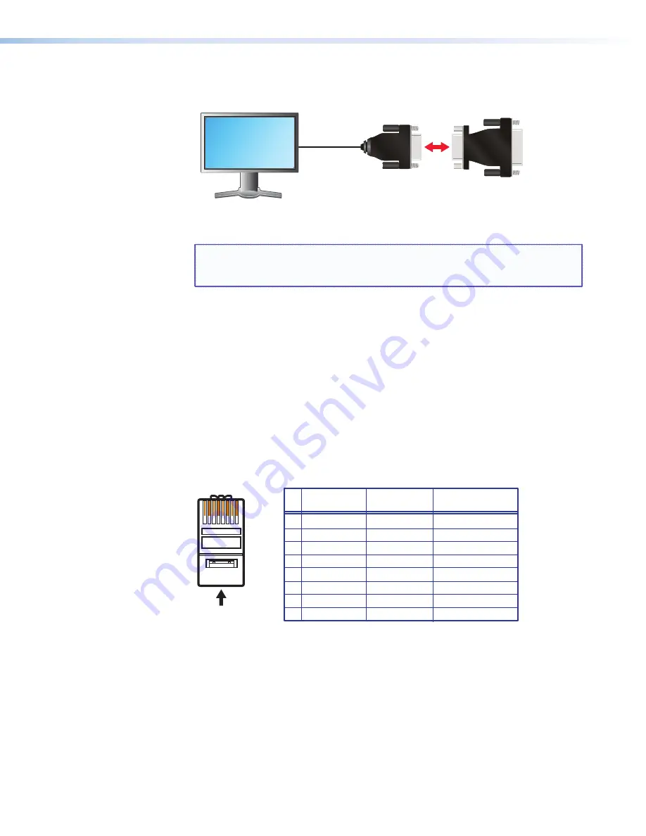
Plug the DVI-A connector of the adapter into the QGE DVI-I Out port.
Analog Monitor
Analog to DVI
Adapter
To QGE 100
DVI I Out Port
Figure 8.
Connecting the Monitor of an Analog Source Computer to the
Analog to DVI Adapter
NOTE:
If you use a monitor cable or adapter other than the one provided with
the QGE 100, ensure that all pins are properly interconnected; otherwise,
the computer graphics card or monitor may not operate correctly.
Connecting the QGE 100 to the Network
Source content that is captured by the QGE 100 from a source computer is transmitted to
a viewing device via TCP/IP over an Ethernet network.
Connection Procedure
Connect the QGE to your network as follows:
1.
Connect a standard straight-through Ethernet patch cable (not supplied) between the
LAN port on the QGE 100 rear panel to a switch or router that is connected to the
same network as your viewing device. (A shielded twisted pair cable is recommended
for this connection.) The network port on the router or switch must be capable of
supporting a 100BASE-T connection.
A cable that is wired the same at both ends is called a "straight-through"
cable, because no pin or pair assignments are swapped.
RJ-45
Connector
Insert Twisted
Pair Wires
12345678
Pins:
Straight-through Cable
End 1
End 2
Pin
1
2
3
4
5
6
7
8
Wire Color
Blue
White-blue
White-brown
Brown
Wire Color
T568B
T568B
White-orange
White-orange
Orange
Orange
White-green
White-green
Blue
White-blue
Green
Green
White-brown
Brown
Function
RD+ (+ data receive)
TD- (- data transmit)
TD+ (+ data transmit)
NC
NC
NC
NC
RD- (- data receive)
Figure 9.
RJ-45 Connector Wiring


