background image

Serial Communication, cont’d

DVS 304 • Serial Communication

3-10

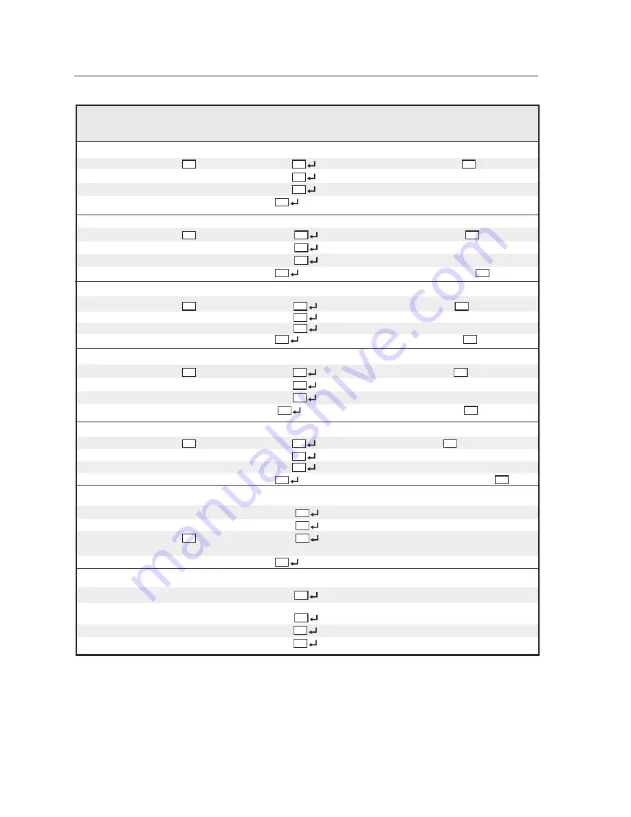
Command/response table for SIS commands (continued)

Command

ASCII Command Response

  Additional description

(host to scaler)

(scaler to host)

Detail Filter

Set detail level

X85

 D

Shp 

X85

Specify the detail level to 

X85

.

Increment up

+ D

Shp 

X85

Increase the detail level.

Increment down

 – D

Shp 

X85

Decrease the detail level.

View detail value

D

X85

Show the detail setting.

Horizontal Shift

Specific value

X86

H

Hph 

X86

Set horizontal centering to 

X86

 .

Increment up

+ H

Hph 

X86

Shift window right.

Increment down

 – H

Hph 

X86

Shift window left.

View

H

X86

Horizontal centering value is 

X86

.

Vertical Shift

Specific value

X86


/

Vph 

X86

Set vertical centering to 

X86

.

Increment up

+ /

Vph 

X86

Shift window down.

Increment down

– /

Vph 

X86

Shift window up.

View

/

X86

Vertical centering value is 

X86

.

Horizontal Size

Specific value

X87

:

Hsz 

X87

Set horizontal sizing to 

X87

.

Increase Size

+:

Hsz 

X87

Widen the window.

Decrease Size

–:

Hsz 

X87

Make the window narrower.

View

:


X87

Horizontal sizing value is 

X87

.

Vertical Size

Specific value

X87

;

Vsz 

X87

Set vertical sizing to 

X87

.

Increase Size

+;

Vsz 

X87

Make the window taller.

Decrease Size

–;

Vsz 

X87

Make the window shorter.

View

;

X87

Vertical sizing value of window is 

X87

.

Zoom Mode

Zoom in

+ {

Zom 

X88

Zoom in making the window larger.

Zoom out

– {

Zom 

X88

Zoom out making the window smaller.

Set Zoom value

X88

 {

Zom 

X88

Set Zoom percentage from 100% (default) to
200%.

View

{

X88

View Zoom percentage.

Pan

Right

- 1#

Hpn 

X89

Left

+1#

Hpn 

X89

U p

- 2#

Vpn 

X89

Down

+2#

Vpn 

X89

im Vertrieb von

            CAMBOARD Electronics

www.camboard.de

Tel. 07131 911201
Fax 07131 911203

[email protected]

Содержание Digital Video Scaler Series

Страница 1: ...S 304 68 1039 01 Rev A 08 05 Digital Video Scaler Series DVS 304 DVS 304 D DVS 304 A DVS 304 AD im Vertrieb von CAMBOARD Electronics www camboard de Tel 07131 911201 Fax 07131 911203 ce info camboard...

Страница 2: ...o sobre la presencia de elementos con voltaje peligroso sin protecci n aislante que puedan encontrarse dentro de la caja o alojamiento del producto y que puedan representar riesgo de electrocuci n Pre...

Страница 3: ...t is the same for both outputs Step 5 for DVS 304 A or 304 AD only Connect up to four balanced or unbalanced stereo audio input devices to the DVS 304 as shown below Each audio input has a 3 5 mm 5 po...

Страница 4: ...Display DVS 304 Application example INPUTS OUTPUT VID 1 2 3 4 Y VID B Y H HV R R Y V G Y B B Y RS 232 LAN RESET ACT LINK RGB R Y Y B Y YC SDI R Y C RGB R Y Y B Y YC VID I N P U T O U T P U T 50 60 Hz...

Страница 5: ...ENU MENU INPUT CONFIG MENU PICTURE CONTROL MENU OUTPUT CONFIG MENU AUDIO CONFIG MENU NEXT MENU MEMORY PRESETS Power on EXTRON DVS 304 2 sec 2 sec INPUT 1 COMPOSITE 60 736 01 FW version 1 00 2 sec 2 se...

Страница 6: ...fy the width in pixels of the total image area sampled Pixel phase Adjust the pixel sampling point for a selected input Horizontal start Select for the left edge of the active video Vertical start Sel...

Страница 7: ...1 2 3 NEXT NEXT Saving SAVE memory presets Save the currently selected input s picture control information Up to 3 presets per input can be selected N A is the default and saved Save a preset by pres...

Страница 8: ...OFF no OSD to 5 seconds in 1 second steps Test patterns Off Crop Alternating pixels Color bars IP CONFIG ADVANCED CONFIG MENU NEXT AUTO IMAGE OFF ON AUTO SWITCH OFF ON NEXT NEXT NEXT RGB DELAY 0 0 se...

Страница 9: ...ut EXE MODE DISABLED Disable Executive Mode 2 sec INPUT 1 COMPOSITE OUTPUT 1024 x 768 60 Default Cycle 2 sec Menu Press for 2 seconds Next 10 sec timeout 2 sec INPUT 1 COMPOSITE OUTPUT 1024 x 768 60 D...

Страница 10: ...D menu display and controls 2 8 Menus Configuration and Adjustments 2 9 Moving through menus by using front panel controls 2 9 Menu overview 2 9 Start auto image 2 10 Input configuration 2 11 Input 1...

Страница 11: ...r communications 3 2 Scaler initiated messages 3 2 Using the command response tables 3 2 Copyright information 3 3 Password information 3 3 Error responses 3 4 References to errors 3 4 Symbol definiti...

Страница 12: ...irmware upgrade 4 6 File Management 4 7 Control 4 8 User Control page 4 8 Presets page 4 9 PIP Setup page 4 11 Appendix A Appendix A 1 Specifications A 2 Part Numbers and Accessories A 5 Included part...

Страница 13: ...Chapter One Introduction About this Manual About the DVS 304 DVS 304 D DVS 304 A DVS 304 AD Features im Vertrieb von CAMBOARD Electronics www camboard de Tel 07131 911201 Fax 07131 911203 ce info cam...

Страница 14: ...he DVS 304 scales from composite video S video component Y R Y B Y video and RGB video to computer video RGBHV RGBS RGsB or HD component It can also output to two separate display devices via individu...

Страница 15: ...times for simultaneous output Four ways to control the scaler The scaler s front panel a computer or other RS 232 control device the optional IR 902 remote control and GlobalViewer can all be used to...

Страница 16: ...includes IR 902 remote control Extron s IR 902 part 70 495 01 is an infrared remote control which replicates most of the front panel controls of the DVS 304 except the Menu and Next buttons SDI input...

Страница 17: ...res Front Panel Features Menus Configuration and Adjustments Resetting an Input Resetting the Unit System Reset Front Panel Lockout Executive Mode IR 902 Infrared Remote Control im Vertrieb von CAMBOA...

Страница 18: ...ottom side of the unit and place the unit in the desired location Rack mounting the DVS 304 1 If feet were installed on the bottom of the DVS 304 remove them 2 Place the DVS 304 on one half of the 1U...

Страница 19: ...ove them 2 Attach the included rack through desk mounting brackets part 70 077 03 to the unit using eight machine screws supplied with the mounting kit 8 Screw 4 Plcs Each Side Figure 2 2 Attaching th...

Страница 20: ...UT 50 60 Hz 100 24 0V 3A 2 1 3 4 L R L R L R L R L R AU DIO VID 1 2 3 4 Y VI D B Y H HV R R Y V G Y B B Y RS 23 2 LA N RE SE T AC T LIN K RG B R Y Y B Y YC SD I R Y C RG B R Y Y B Y YC VI D I N P U T...

Страница 21: ...io input 3 Audio output Plug one 3 5 mm female five pole captive screw connector for balanced unbalanced variable audio output 4 Video input 1 Composite video Connect a composite video signal to this...

Страница 22: ...nent R Y Y B Y 15 pin HD video output Connect an RGB video display or HD component video display to this HD 15 pin connector RGB R Y Y B Y Both 8 outputs are buffered and can be connected simultaneous...

Страница 23: ...This connector provides for two way RS 232 communication See chapter 3 Serial Communication for information on how to install and use the control software and SIS commands RS 232 5 9 1 6 The default p...

Страница 24: ...GB pass through YUVi YUVp S video and composite video Menu navigation buttons 2 Menu button Use this button to enter and move through the main menu system in the DVS 304 See the Menus Configuration an...

Страница 25: ...ust vertical knob to scroll through submenu options and to make adjustment selections Refer to the flowcharts in this chapter and to specific sections for explanations on knob adjustments Menu overvie...

Страница 26: ...art auto image Auto imaging allows you to auto size and auto center the selected image to fill the screen The processor measures the sync frequencies of an incoming video source and uses an internal t...

Страница 27: ...XXX 08 NEXT NEXT NEXT NEXT H START V 128 128 H ACTIVE V XXX XXX NEXT FILM MODE OFF ON Displays only when applicable Displays only when applicable Displays only when applicable Displays only when appli...

Страница 28: ...erts back to the last video type that was assigned to it Picture control The Picture Control menu includes all of the picture settings for the scaler including positioning sizing horizontal and vertic...

Страница 29: ...BS RGsB Y R Y B Y Sync polarity combinations H Neg V Neg default H Neg V Pos H Pos V Neg H Pos V Pos NOTE This information only appears when the sync polarity is applicable and is based on the selecte...

Страница 30: ...ed on input Output Signal Using either the Adjust horizontal or Adjust vertical knob select the output video format required by the display RGBHV default RGBS RGsB Y R Y B Y Sync Polarity The display...

Страница 31: ...and the options for each setting NEXT IN1 SAVE N A 1 2 3 IN1 CLEAR N A 1 2 3 NEXT NEXT Saving SAVE memory presets Save the currently selected input s picture control information Up to 3 presets per in...

Страница 32: ...splay the LCD message Input X Memory Y where X refers to the input 1 to 4 and Y refers to the preset 1 to 3 The absence of any saved presets will not display the Input X Memory Y LCD message for the a...

Страница 33: ...s OSD label duration Can be set from 0 OFF no OSD to 5 seconds in 1 second steps Test patterns Off Crop Alternating pixels Color bars IP CONFIG ADVANCED CONFIG MENU NEXT AUTO IMAGE OFF ON AUTO SWITCH...

Страница 34: ...tch switching You can set the blanking period from 0 to 5 seconds in 0 5 second steps OSD label Use the On Screen Display OSD label menu to determine the time allotment for an input label or a user de...

Страница 35: ...ge in configuration except positioning of the PIP window is saved to that input even after the PIP mode is not longer active The PIP window input is listed under the default cycle on front panel menu...

Страница 36: ...MENU AUDIO CONFIG Audio models only MENU NEXT Figure 2 19 Exit menu Resetting an Input Each input of the DVS 304 scaler can be reset to its default value by holding down the specific input button unt...

Страница 37: ...t Turns DHCP off Turns all events off The Reset LED flashes 4 times in quick succession during reset Mode 5 performs a complete reset to factory defaults except the firmware Does everything mode 4 doe...

Страница 38: ...later in this chapter for more information When executive mode is active all functions and adjustments can still be made through RS 232 control For details on RS 232 control see chapter 3 Serial Commu...

Страница 39: ...ter 3 Serial Communication for details The topmost part of the IR 902 features memory preset buttons input switching picture in picture PIP volume and four input selection buttons 1 2 3 4 The middle p...

Страница 40: ...Installation and Operation cont d DVS 304 Installation and Operation 2 24 im Vertrieb von CAMBOARD Electronics www camboard de Tel 07131 911201 Fax 07131 911203 ce info camboard de...

Страница 41: ...304 3 Chapter Three Serial Communication RS 232 Programmer s Guide Control Software for Windows im Vertrieb von CAMBOARD Electronics www camboard de Tel 07131 911201 Fax 07131 911203 ce info camboard...

Страница 42: ...ich signals the end of the response character string A string is one or more characters Scaler initiated messages When a local event such as a front panel selection or adjustment takes place the DVS 3...

Страница 43: ...her method Data Data is directed to a specified port and must be encoded if non alphanumeric The Command response table for Simple Instruction Set SIS commands later in this chapter lists the commands...

Страница 44: ...1 Invalid preset number E12 Invalid port number E13 Invalid parameter E14 Not valid for this configuration E17 Invalid command for signal type E22 Busy E24 Privilege violation E25 Device not present E...

Страница 45: ...t before terminating the connection min 0 max 32767 and default 10 100 ms The response is returned with leading zeros In RS 232 commands X17 is optional X18 Hardware MAC address xx xx xx xx xxxx X19 S...

Страница 46: ...tion rate in seconds 0 255 max default 0 clear The response is returned with leading zeros 1 11 entry without password goes to the level specified if an admin password exists The response as returned...

Страница 47: ...sync format 0 RGBHV default 1 RGBS 2 RGsB 3 Y R Y B Y X95 Memory presets 1 to 3 X96 Input 4 presets 1 to 128 X97 Test pattern 0 to 3 X98 OSD display setup 0 to 5 seconds in 1 second steps X99 Auto ima...

Страница 48: ...tive window Vertical Start Specify a value X75 Vst X75 Set vertical location of first active line in active window Increment value Vst X75 Increment to a higher vertical start position Decrement value...

Страница 49: ...mt1 Blanks selected input Disable Blanking 0B Vmt0 Displays selected input View B X80 View the blanking status Color Specific value X85 C Col X85 Sets color level to X85 Increment up C Col X85 Increme...

Страница 50: ...crement up Vph X86 Shift window down Increment down Vph X86 Shift window up View X86 Vertical centering value is X86 Horizontal Size Specific value X87 Hsz X87 Set horizontal sizing to X87 Increase Si...

Страница 51: ...y Recall Preset 2 X96 2Rpr X96 Recalls input 4 preset X96 Save Preset 2 X96 2Spr X96 Saves input 4 parameters to preset X96 Write Read input preset name Write preset name Esc X96 X84 NG Nmg X96 X84 Na...

Страница 52: ...lected input Disable 0 F f Frz 0 Unfreeze selected input View F f X80 Show the freeze status RGB delay time On 3 X107 Dly X107 Set RGB delay to X107 x 0 5 seconds View setting 3 X10⁷ View RGB delay se...

Страница 53: ...P mode is On Tke0 Swap content between main and PIP window PIP mode audio follow Audio model only Set 19 X106 Ald X106 Select audio follow setting in PIP mode View 19 X106 View audio follow status Gen...

Страница 54: ...rently running A caret indicates bad checksum invalid load Question marks indicate version not loaded Firmware version requests Query firmware version Q or 1Q Q or 1Q X11 Show the processor s firmware...

Страница 55: ...command to find out which version of the firmware if any was uploaded into the processor after it left the factory Example 4Q 4Q 1 01 1 46 DVS 304 Series Mon 17 Jan 2005 17 03 46 GMT In this example t...

Страница 56: ...from event X35 buffer X36 offset by X37 Start events 24 27 Esc 1AE W1AE Ego Initiate all programmed events Stop events 24 27 Esc 0AE W0AE Est Stop all programmed events Read number of events running E...

Страница 57: ...d with DVS304 a combination of the model name and the last 3 pairs of the hex numbers in the processor s MAC address e g DVS304 00 02 3d Read unit name Esc CN WCN X12 X12 is the processor s current un...

Страница 58: ...ST should be turned off in Hawaii American Samoa Guam Puerto Rico the U S Virgin Islands the eastern time zone part of Indiana and Arizona excluding the Navajo Nation 0 off ignore 1 on Read daylight s...

Страница 59: ...acters The password is case sensitive Special characters spaces or symbols are not allowed Clear administrator password 24 Esc CA W 20CA Ipa Clear remove all passwords administrator and user A user pa...

Страница 60: ...ic on the network If you want to use the Verbose mode with a processor connected via Ethernet this mode must be set to On each time you reconnect to the processor Read Verbose mode Esc CV WCV X22 Read...

Страница 61: ...P2 timedate 2 uptime 2 connections 3 Client IP3 timedate 3 uptime 3 connections n Client IPn timedate n uptime n connections n 1 total clients connections available File commands Read Direct Access po...

Страница 62: ...ry A directory does not actually exist until a file has been copied into the path Move back to root directory Esc CJ W 2FCJ Dir Move up one directory Esc CJ W 2E 2ECJ Dir path directory View current d...

Страница 63: ...rogram require approximately 32 MB of hard disk space To install the software on the hard drive 1 Insert the CD Rom into your CD drive The disk starts automatically 2 If the disk does not start automa...

Страница 64: ...O Config button to configure the inputs from the I O Configuration Window 4 Click the Input Config advanced button for advanced input parameters as shown below 3 24 im Vertrieb von CAMBOARD Electroni...

Страница 65: ...304 Help icon in the Extron Electronics group or folder For explanations of buttons or functions click on the tabs in the help screen to reach the desired screen Use a mouse or the Tab and Enter keys...

Страница 66: ...Serial Communication cont d DVS 304 Serial Communication 3 26 im Vertrieb von CAMBOARD Electronics www camboard de Tel 07131 911201 Fax 07131 911203 ce info camboard de...

Страница 67: ...4 Chapter Four Ethernet Control Accessing and Using the Web Server Navigating the Default Web Pages im Vertrieb von CAMBOARD Electronics www camboard de Tel 07131 911201 Fax 07131 911203 ce info camb...

Страница 68: ...ld If the local system administrators have not changed the value the factory specified default 192 168 254 254 is the correct value for this field 4 If you want the browser to display a page other tha...

Страница 69: ...age nortxe_index html figure 4 2 shown below also known as the System Status page Navigating the Default Web pages The DVS 304 default Web pages include four tabs Status Configuration File Management...

Страница 70: ...s are invalid in the name space and DHCP The Dynamic Host Configuration Protocol DHCP is an Internet protocol for automating the configuration of computers that use TCP IP DHCP can be used to automati...

Страница 71: ...be used if the DVS 304 and the mail server are not on the same subnet The gateway IP address has the same validity rules as the system IP address Subnet Mask field The Subnet Mask field is used to det...

Страница 72: ...ection entering SIS commands see chapter 3 Serial Communication or using the Windows based control program to access the DVS 304 is password protected Connecting via the RS 232 port entering SIS comma...

Страница 73: ...ere you saved the firmware upgrade file Select the file Valid firmware files must have the file extension S19 Any other file extension is not a firmware upgrade The original factory installed firmware...

Страница 74: ...d the File Management screen figure 4 7 is displayed 2 Find the file you wish to delete under the Files list 3 Click the delete button of the file to be deleted If you wish to delete additional files...

Страница 75: ...w selected input When only one box is checked and the other is cleared i e different audio and video sources are selected this is a breakaway You can also define the volume level mute audio and set th...

Страница 76: ...trol link on the left side of the page The User Control page appears figure 4 8 4 Click the button for the input 4 5 Make changes to the picture control settings e g aspect ratio zoom brightness etc Y...

Страница 77: ...e page The PIP Setup page appears figure 4 10 4 Use the drop down menu to set the size of the subordinate PIP picture 5 Use the drop down menu to choose the appropriate PIP input See chapter 2 Install...

Страница 78: ...nd position of the main and PIP windows Audio DVS 304 A only Use the Audio Follows radio button shown below to assign audio to either the main image or the PIP image im Vertrieb von CAMBOARD Electroni...

Страница 79: ...endix Appendix Specifications Part Numbers and Accessories Serial Digital Interface SDI Card Installation im Vertrieb von CAMBOARD Electronics www camboard de Tel 07131 911201 Fax 07131 911203 ce info...

Страница 80: ...gitalsampling 24 bit 8 bits per color 13 5 MHz standard Colors 16 78 million Video output Number signal type 2 scaled or pass through RGBHV RGBS RGsB or scaled component video Y R Y B Y Connectors 5 f...

Страница 81: ...dB channel to channel Maximum level Hi Z 21 dBu balanced or unbalanced at 1 THD N Maximum level 600 ohm 15 dBm balanced or unbalanced at 1 THD N Output volume range 0 to 100 52 dB to 0 dB in 0 5 dB in...

Страница 82: ...wide 4 4 cm H x 22 2 cm W x 26 7 cm D Depth excludes connectors and knobs DVS 304A DVS 304AD 1 75 H x 17 5 W x 10 5 D 1U high full rack wide 4 4 cm H x 44 4 cm W x 26 7 cm D Depth excludes connectors...

Страница 83: ...d parts Part number DVS 304 A or DVS 304 AD 60 736 02 04 Rubber feet self adhesive 4 Rack and through desk mounting kit 70 077 03 IECpowercord 27 044 01 Tweeker small screwdriver User s Manual DVS 304...

Страница 84: ...efore opening the enclosure 2 Remove the scaler from the rack or furniture 3 Remove the cover of the scaler the top half of the enclosure by removing the screws then lifting the cover straight up figu...

Страница 85: ...ar SDI connector opening 6 The SDI card has a 20 pin socket on the underside which should align with the 20 pins on the main circuit board Be sure to align the pins properly in order to prevent bendin...

Страница 86: ...Appendix cont d DVS 304 Appendix A 8 im Vertrieb von CAMBOARD Electronics www camboard de Tel 07131 911201 Fax 07131 911203 ce info camboard de...

Страница 87: ...s ExtronElectronics Europe 1001 East Ball Road Beeldschermweg 6C Anaheim CA 92805 USA 3821AHAmersfoort The Netherlands Asia Japan Extron Electronics Japan Extron Electronics Asia KyodoBuilding 135 Joo...

Страница 88: ...e Netherlands 31 33 453 4040 Fax 31 33 453 4050 Extron Electronics Asia 135 Joo Seng Road 04 01 PM Industrial Building Singapore 368363 65 6383 4400 Fax 65 6383 4664 Extron Electronics Japan Kyodo Bui...

Отзывы: