2015-03-16 13:02:26 C:\Users\Rickard\OneDrive - Excillum AB\electronics-Excillum\system wiring diagrams\Safety System interface\Electron Gun Safety System Interface\P-029-0001 Rev 02 - Electron gun safety system interface.sch (Sheet: 1/1)
240 ohm
Страница 1: ...Revision 19 November 2016 MetalJet D2 Operating manual ...
Страница 2: ...eir respective owners Excillum MetalJet MetalJet D1 MetalJet D2 and MetalJet D2 are registered trademarks or trademarks of Excillum AB Excillum s MetalJet sources are protected by several patents including but not limited to US Patents No US 6 711 233 US8 170 179 US 8 681 943 US 8 837 679 US 9 171 693 US 9 245 707 and Chinese Patents No CN 01 816396 3 ZL200780026317 0 ZL200980155094 7 ZL 200980158...
Страница 3: ...ional information or purchase of spare parts The serial numbers and the manufacturing year may be found on the identification tag on the rear of each sub assembly unit close to the electrical power connector System article number G 020 0037 rev 02 Sub assembly unit Article number Serial number Manufacturing year Electron gun x ray head G 020 0020 EXH Pump box G 035 0033 PBO X ray system controller...
Страница 4: ...dard exit window 1 8 1 3 3 3 Without x ray shutter using increased cone angle exit window 1 9 2 SAFETY 2 1 2 1 Safety precautions 2 1 2 1 1 Qualified personnel 2 1 2 1 2 Partly completed machinery 2 1 2 1 3 Operating manual 2 1 2 1 4 X ray radiation 2 2 2 1 5 Electricity and high voltage 2 2 2 1 6 High pressure 2 3 2 1 7 Heat 2 4 2 1 8 Magnetic fields 2 4 2 1 9 Poisoning hazard 2 5 2 2 Proper use ...
Страница 5: ...m 4 25 4 4 1 High voltage controller 4 25 4 4 2 Electron gun 4 25 4 5 Operating conditions 4 27 4 5 1 Ambient conditions 4 27 4 5 2 Ventilation 4 27 4 5 3 Cooling water 4 27 4 6 System integration 4 28 4 6 1 System accessibility 4 28 4 6 2 Network connectivity 4 30 5 OPERATION 5 1 5 1 Introductory notes on source operation 5 1 5 1 1 Starting jet pump 5 1 5 1 2 Leave MetalJet D2 system in On or Rea...
Страница 6: ...eration 5 14 5 10 1 Turning on x ray generation 5 14 5 10 2 Change emission power and spot size 5 14 5 10 3 Turning off x ray generation 5 14 5 10 4 Turning off the MetalJet D2 source 5 14 5 11 System Settings 5 16 5 12 Software API 5 17 6 MAINTENANCE AND SERVICE 6 1 6 1 Vacuum system 6 2 6 1 1 Roughing pump 6 2 6 1 2 Turbopump 6 2 6 2 Jet system 6 2 6 2 1 Jet pump lubricants 6 2 6 2 2 Jet pump di...
Страница 7: ...wn for shorter periods 7 1 7 2 Shutting down for longer periods 7 1 7 3 Restarting after longer shutdown 7 1 7 4 Disposal 7 1 8 MALFUNCTION AND TROUBLESHOOTING 8 1 9 CUSTOMER SUPPORT 9 1 9 1 System log files 9 1 9 2 Remote support 9 2 10 SPARE PARTS 10 1 11 TECHNICAL DATA 11 1 ...
Страница 8: ...e safety instructions in this operating manual are the result of a risk assessment in accordance with SS EN 12100 2010 Safety of Machinery General principles for design Risk assessment and risk reduction formerly SS EN ISO 14121 Safety of Machinery Risk Assessment In this document the following hazard levels and information are considered DANGER Immediate danger Death or very severe injuries may o...
Страница 9: ...s x rays This x ray source is suitable for use in any x ray application where increased x ray source brightness is desired Increased source brightness can be used in order to decease the exposure time or increase the resolution of the x ray image 1 3 2 1 Liquid metal circulation loop The jet pump displaces liquid metal from the reservoir in the low pressure flex hose assembly to the high pressure ...
Страница 10: ...h vacuum pump turbopump 7 Ventilation valve 8 Fore vacuum hose 9 High voltage cable connected to high voltage feedthrough 10 Interconnecting cables 11 X ray head PCB cross connect board 12 Electron optics 13 Exit window not visible it is underneath the shutter 14 Flex hose assembly 15 Jet brake 16 Upper cooling block 17 Shutter Figure 1 1 The main components of the electron gun x ray head 1 2 3 8 ...
Страница 11: ... 2 Upper cooling block 3 Jet brake 4 Flex hose assembly 5 Fore vacuum hose 6 Cooling water inlet 7 Cooling water outlet 8 Pulsation dampener 9 Diaphragm guard 10 Jet pump 11 Outlet check valve 12 Pump head 13 Inlet check valve 14 Liquid metal filling valve 15 Filling valve adapter 16 Lower cooling block 17 Roughing pump 18 Heater fan 19 Pump box electronics ...
Страница 12: ...METALJET D2 INTRODUCTION Revision 19 November 2016 Page 1 5 5 6 7 10 1 8 9 11 0 2 1 3 12 13 0 14 0 15 0 16 0 17 0 18 19 4 ...
Страница 13: ...efinition of left and right is indicated in Figure 1 3 using a red arrow for the left handed system and a green arrow for the right handed system Figure 1 3 MetalJet D2 system configured with the x ray output on both sides dual port Red arrow indicate output direction of left handed system and green arrow indicate output direction of a right handed system The output direction can be reconfigured i...
Страница 14: ...out a shutter it can be configured with a standard exit window or an exit window with an increased cone angle The figures in Sections 1 3 3 1 1 3 3 3 show minimum source to object distance exit window diameter and x ray emission cone angle for each of these configurations 1 3 3 1 With x ray shutter Figure 1 4 Schematic of the x ray head with x ray shutter mounted ...
Страница 15: ...ETALJET D2 INTRODUCTION Revision 19 November 2016 Page 1 8 1 3 3 2 Without x ray shutter using standard exit window Figure 1 5 Schematic of the x ray head without x ray shutter using standard exit window ...
Страница 16: ...NTRODUCTION Revision 19 November 2016 Page 1 9 1 3 3 3 Without x ray shutter using increased cone angle exit window Figure 1 6 Schematic of the x ray head without x ray shutter using increased cone angle exit window ...
Страница 17: ... 2006 42 EC and is therefore intended to be incorporated into or assembled with other machinery or partly completed machinery in order to function properly It is the responsibility of the machinery integrator to make sure that the final machinery meets all local safety regulations such as radiation protection and all other applicable regulations such as CE compliance Machinery Directive EMC Direct...
Страница 18: ... urged to use them to protect against unnecessary radiation exposure DANGER X ray radiation can be a health hazard X ray equipment may cause injury or even death if improperly used The MetalJet D2 apparatus is a source of x ray radiation which is harmful to the human body To avoid health problems arising from exposure to x rays exercise the greatest possible caution when using this x ray source Th...
Страница 19: ...1 6 High pressure The MetalJet D2 source has unlike conventional x ray sources a liquid metal jet anode The metal jet is generated by forcing a liquid metal through a small orifice The pressure generated by the metal pump is 190 bar Therefore only properly trained service personnel should be permitted to service the diaphragm pump or any part of the tubing system connected to the pump WARNING High...
Страница 20: ... The MetalJet D2 source may also be sensitive to ferromagnetic materials and other materials with a high relative magnetic permeability close to the electron gun x ray head These may affect the magnetic fields generated by the electron optics and the focusing lens and thus cause a severe loss of x ray output performance As a consequence of the influence of materials with a high relative permeabili...
Страница 21: ... get hurt by beryllium fragments This is why you must wear safety goggles and gloves when cleaning the instrument after such an incident Disposal of beryllium must comply with all applicable national state and local laws and regulations If breakage of a beryllium window occurs proceed as follows 1 Avoid touching breathing or swallowing the particles and do not allow the particles to come into cont...
Страница 22: ...in Section 2 2 above especially but not limited to Using accessories or spare parts not mentioned in this operating manual without authorization from Excillum Pumping other liquids gases slurries or similar in the metal jet loop than what is stated in the confirmation of the purchase order If permitted liquids or similar is not stated in the confirmation of the purchase order written approval from...
Страница 23: ...ng Use the three lifting handles on the side to lift the pump box see Figure 3 1 The pump box must be lifted by at least two persons using correct lifting technique to avoid personal injuries as well as damage to the pump box Figure 3 1 Use the three lifting handles when moving the pump box The third handle is on the far side of the pump box not shown in the image The electron gun x ray head must ...
Страница 24: ...You may injure yourself and or the equipment 3 2 Storage The MetalJet D2 source should only be stored in an upright position Check that all openings on the MetalJet D2 source are properly closed in order to prevent dust dirt or other contaminants from entering the system during storage Store the MetalJet D2 source in the temperature range 20 40 C 68 104 F Store the MetalJet D2 source in a dry plac...
Страница 25: ...etalJet D2 source unpack it and make sure there are no transport damages and that everything looks ok 4 Without removing any of the liquid metal loop transport seals mechanically install the pump box source head and the two electronics control racks in their intended positions and make sure that the liquid loop appears to be able to mate once transport seals are removed see Section 4 3 1 5 If you ...
Страница 26: ...ivery Surfaces exposed to vacuum and high voltage insulator ends on the cables should never be handled with bare hands Use clean room gloves to keep parts free from fingerprints and other contaminants when setting up the MetalJet D2 source 4 3 1 Mounting of sub assembly units The electron gun x ray head and the pump box are designed to be semi rigidly connected to each other by the supply high pre...
Страница 27: ...s the x ray head In order not to over stretch or over compress the metal jet loop components during these adjustments there are limitations to their vertical positions in relation to each other see Figure 4 2 Minimum distance pump box lid to lower end of front cover 45 cm Maximum distance pump box lid to lower end of front cover 55 cm In addition it is also important that the jet exit port see Sec...
Страница 28: ...ovember 2016 Page 4 4 Figure 4 2 The minimum distance from the lid of the pump box and the base plate is 45 cm and the maximum distance is 55 cm Also the jet exit port should be placed straight above the rectangular hole in the pump box lid ...
Страница 29: ...METALJET D2 INSTALLATION Revision 19 November 2016 Page 4 5 Figure 4 3 The jet exit port should be placed straight above the hole in the pump box lid ...
Страница 30: ...ate onto a support with dimensions smaller than the base plate to avoid that the side covers take up the weight of the x ray head The center of gravity for the x ray head is indicated in Figure 4 4 The pump box can either be rack mounted or positioned directly on the floor Use the side brackets on the front of the pump box to attach the pump box to a 19 rack see Figure 4 6 or to fasten it relative...
Страница 31: ...ng to this image the electron gun x ray head seen from below Mount the x ray system controller and the x ray high voltage controller properly into a 19 rack located close to the electron gun x ray head and the pump box Figure 4 6 Use the side brackets on the front of the pump box to attach the pump box to a 19 rack ...
Страница 32: ... port 1 Remove transportation seals from the flex hose assembly and jet exit port before connecting these to each other Store the transportation seals for future sealing purposes NOTE Be careful not to scratch the sealing surfaces during assembly 2 Connect the top end of the flex hose assembly to the jet exit port using a 14x3 mm Viton o ring and six M4x12 screws see Figure 4 8 Figure 4 8 Connect ...
Страница 33: ...pump inside the x ray head with cooling water is routed from the pump box along the flex hose assembly into the x ray head through the opening circled in red in Figure 4 9 The return hose is connected to the fitting of the upper cooling block circled in green in Figure 4 9 Both supply and return hoses are plugged and stored inside the pump box during shipping The labels attached to the hoses indic...
Страница 34: ...n through system subassemblies Follow the instructions below to connect the supply hose for the turbopump and the return hose from the upper cooling block 1 Remove the right hand cover of the x ray head using a 2 mm Allen wrench to expose the turbopump cooling block and route the supply hose through the opening indicated in Figure 4 9 Connect the water hose to the turbopump cooling block and make ...
Страница 35: ...METALJET D2 INSTALLATION Revision 19 November 2016 Page 4 11 Figure 4 11 X ray head with right hand cover removed Turbo pump cooling block circled in red ...
Страница 36: ...r 2016 Page 4 12 2 Connect the return hose to the fitting on the upper cooling block circled in green in Connect the water Figure 4 12 Upper cooling block with water hoses connected and flow direction indicated blue arrows To lower cooling block ...
Страница 37: ... VCR gasket with its retainer onto the top end of the nozzle assembly b Screw on and tighten the nut on the high pressure tubing using your fingers only c Use two 19 mm wrenches to tighten the nut relative the top end of the nozzle assembly another 45 The wrench holding the nozzle assembly should not rotate Figure 4 13 Connect the port on the high pressure tubing to the nozzle assembly using an un...
Страница 38: ...e with the melting point of the alloy used Contact Excillum for further information about water chiller requirements if an external water cooling solution is preferred or required MetalJet D2 systems are currently delivered with a standalone water to air heat exchanger Excillum document P 020 0026 Rev 01 ThermoFlex Series installation contains detailed installation instructions for this chiller 1 ...
Страница 39: ...09 0153 5 m E 009 0233 10 m B2 x ray system controller B2 x ray head E 009 0036 5 m E 009 0238 10 m U3 x ray system controller U3 x ray head E 009 0079 5 m E 009 0237 10 m U5 x ray system controller U5 x ray head E 009 0038 5 m E 009 0235 10 m SN x ray high voltage controller SN x ray head E 009 0100 1 5 m D HV x ray system controller D HV x ray high voltage controller E 009 0101 1 5 m A HV x ray ...
Страница 40: ...h voltage generator is built into the x ray high voltage controller in MetalJet D2 70 kV systems see Figure 4 17 Figure 4 16 X ray head from behind showing connectors to x ray system controller and x ray high voltage controller left side Figure 4 17 X ray high voltage controller seen from behind ...
Страница 41: ...tor Avoid excessive twisting or force when inserting cable c Tighten the eight M6x20 screws in a star shaped pattern until fully screwed in Figure 4 18 Connect the tapered end of the high voltage cable to the electron gun according to the instructions above 2 Connect the cable labeled E 009 0065 RC to the RJ45 socket labeled Pull wire Note The purpose of the pull wire is to prevent users from remo...
Страница 42: ...bbed contact is too high put a small amount of silicone oil part number M 00420 on the ribbed contact and smear it out properly b Hand tighten the ring nut c Tighten the grub screw Figure 4 20 Connect the ribbed contact of the high voltage cable to the rear of the x ray high voltage controller unit DANGER High voltage is potentially lethal All sub assembly units must be properly grounded and all c...
Страница 43: ...ontroller seen from behind 1 Connect all interconnecting cables between x ray high voltage controller and the high voltage generator according to Table 4 2 below Cable part number Port 1 Port 2 E 009 0188 1 m 9 Pin D sub GENERATOR CONTROL x ray high voltage controller RS 232 high voltage generator E 009 0189 1 m 15 Pin D sub GENERATOR CONTROL x ray high voltage controller JB1 high voltage generato...
Страница 44: ...tor Avoid excessive twisting or force when inserting cable c Tighten the eight M6x20 screws in a star shaped pattern until fully screwed in Figure 4 23 Connect the tapered end of the high voltage cable to the electron gun according to the instructions above 3 Connect the cable labeled E 009 0065 RC to the RJ45 socket labeled Pull wire Note The purpose of the pull wire is to prevent users from remo...
Страница 45: ...holding the connector flange in position and check for correct HV cable compression by visual inspection on the side of the cable assembly Figure 4 25 Connect the ribbed contact of the high voltage cable to the rear of the x ray high voltage controller unit c The two first rings should be visible but not the third one see Figure 4 26 below Adjust if necessary by removing the four screws and rotati...
Страница 46: ...ge is potentially lethal All sub assembly units must be properly grounded and all cables must be securely attached before turning on the MetalJet D2 source Ensure that all interlocks are connected before energizing the MetalJet D2 source Do not disconnect or bypass any interlocks ...
Страница 47: ...considered optional we highly recommend connecting the common system PE terminal to the Mains inlet PE terminal dashed red line to minimize ground loops that can introduce noise to system sensors Figure 4 27 Schematic showing how to connect the protective earth terminals of the sub modules to the system ground terminal Table 4 3 summarize which sub modules that are rack mounted and also indicate s...
Страница 48: ... system controller 208 240 VAC 50 60 Hz 0 5 kW 208 240 V 2 50 60 Hz 0 5 kW X ray high voltage controller 208 240 VAC 50 60 Hz 0 5 kW 208 240 V 2 50 60 Hz 0 5 kW High voltage controller MetalJet D2 160 kV 208 240 VAC 50 60 Hz 0 8 kW 208 240 V 2 50 60 Hz 0 8 kW Pump box 208 240 VAC 50 60 Hz 2 kW 208 240 V 2 50 60 Hz 2 kW Water chiller See water chiller operating manual Table 4 4 Mains supply specifi...
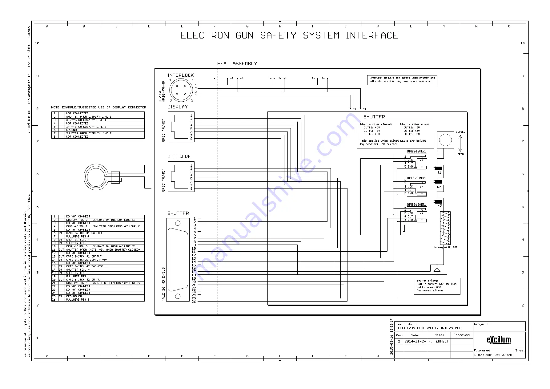
Страница 49: ...mer safety system can be implemented 4 4 1 High voltage controller The high voltage controller has a male 44 pin high density D sub connector labeled X1 It gives access to the safety relays and high voltage monitor outputs The safety relays should only be activated when the customer safety requirements are fulfilled It is the responsibility of the customer to decide what safety level is required I...
Страница 50: ...y driven with separate current limited DC frequency signals Each light emitting diode emits pulses of invisible infrared light when energized by the light curtain s timing and logic circuitry The purpose of using different frequencies is to eliminate potential crosstalk Sensor side logic should then be built to remove the added frequency signal to get the actual state of the sensor Note The shutte...
Страница 51: ...ns See Chapter 11 The MetalJet D2 source should not be placed in a space where it may be exposed to direct sunlight atmospheric agents rain snow ice etc dust or aggressive gases Do not install or use the MetalJet D2 source in explosive environments or those with a high fire risk 4 5 2 Ventilation Do not block the air intakes of the source head pump box and two electronics rack modules 4 5 3 Coolin...
Страница 52: ...ystem IT infrastructure 4 6 1 System accessibility Easy access to the system simplify regular maintenance and service and should be considered during the system design phase Servicing the jet pump benefit from easy access to the pump box from all four sides However in cases where this is not possible access from the front should be prioritized see Figure 4 29 Figure 4 29 Easy access to the pump bo...
Страница 53: ...e radiation shielding covers Figure 4 30 Allow for enough clearance to remove the high voltage cable and high voltage flange during cathode replacement Replacing the nozzle the exit window and performing service to the electron dump require access to the front of the x ray head from different directions see red arrows Figure 4 31 The shutter must be removed in order to access the exit window which...
Страница 54: ...e machine and access files stored on the system controller In most cases connecting a monitor keyboard and a mouse directly to the x ray system controller is only necessary during installation if network settings need to be changed Figure 4 32 Suggested network architecture and capabilities of the x ray system controller We recommend using TightVNC combined with FileZilla or MobaXterm to remote co...
Страница 55: ... about which alloy to choose for a specific application The physical properties of the alloys are also different Refer to the MetalJet D2 service manual Section Start jet pump for instructions on how to prepare the system for starting the jet pump 5 1 2 Leave MetalJet D2 system in On or Ready It is strongly recommended that the MetalJet D2 system is always in either the On state or in the Ready st...
Страница 56: ...nt amounts of metal vapor that can damage the source in various ways The maximum power for a given spot size and shape is therefore limited by software It is important that the spot size is accurately calibrated The spot size is regularly calibrated see 5 9 1 in order to avoid too high power loading It is important to not override this calibration NOTE It is important to not override the calibrate...
Страница 57: ...ake Parametrize system Section 5 8 Set kV setting and put system in Lowpower state HV flangejust attached Condition high voltage by clicking Conditioning Follow the service manualinstructions to Calibrate electron gun emission leakage current Press Clear parametrizations under the Service tab Yes No Jet stable Section 5 8 4 5 8 5 Replacenozzle restart source Section 6 2 4 Set emission power and sp...
Страница 58: ...ns covered by the service manual 5 4 Starting the software and GUI The software is started by the following sequence 1 Turn on the pump box the x ray high voltage controller and the water chiller 2 Turn on the x ray system controller and wait until the desktop is shown see Figure 5 2 Figure 5 2 XCS desktop for the MetalJet D2 system 3 The x ray system controller starts the XCS control software aut...
Страница 59: ...METALJET D2 OPERATION Revision 19 November 2016 Page 5 5 Figure 5 3 The Summary tab is the start view of the GUI for control of the MetalJet D2 source ...
Страница 60: ...g over the exclamation mark Readback values Shows current readings from electron gun power vacuum levels and jet pump pressure Spot info Displays spot size calibration information from last calibration Important messages Shows a subset of important messages from XCS also shown in the Log tab 5 5 The states of the software The software essentially works as a state machine All normal operation of th...
Страница 61: ...f Vent As in the Stop state the vacuum pumps liquid metal jet and x ray generator are turned off In addition in the Vent state the vacuum venting valve is opened effectively bringing the system to atmospheric pressure 5 5 2 Advanced states In addition the following advanced states can be selected by the user Cathodebake Heats the cathode without enabling high voltage The purpose is to remove oxide...
Страница 62: ... registered the click B Change of state in progress yellow button A yellow state button indicates which state the system is currently trying to reach This is also indicated at the top of the GUI which shows the name of the state followed by three dots C Reached state green button A green state button indicates that the system has reached the requested state 5 6 User levels There are three differen...
Страница 63: ... independently for each acceleration voltage Prepare system for parametrization Align electron beam to optical axis Determine jet size and position Characterize focus lens and verify jet stability Characterize linefocus coils After the parametrization is completed it is possible to set the electron beam power spot size and position in relation to the liquid metal jet 5 8 1 Prepare system for param...
Страница 64: ...under last images and inspect the image If the system is ok the image of the electron dump should be a round circle free from metal debris see Figure 5 6 left image Figure 5 6 Deflectorscan of clean left and contaminated right electron beam dump aperture 8 If the alignment algorithm finishes without errors proceed to Section 5 8 3 The Align button will turn green if no errors occur 9 If the mechan...
Страница 65: ...at the determination of the size and position of the jet is performed correctly 5 8 4 Characterize focus lens and verify jet stability The next step is to map up electron beam spot sizes for a number of different focus lens settings and to verify the liquid metal jet stability 12 Go to the States tab and click the Focus button The electron beam will be swept across the liquid metal jet multiple ti...
Страница 66: ...cus routine should be run again This will improve the spot size accuracy If the transition in the edges is not smooth it is a strong indication that the jet is unstable In that case the nozzle needs to be replaced and the parametrization routine must start over from Section 5 8 3 Refer to Section 6 2 4 for further instructions Figure 5 8 The image shows a straight hourglass shape with gradual tran...
Страница 67: ...adjusted for the focus lens hysteresis effect after every change of electron beam spot size The calibration routine measures the spot size by sweeping the electron beam It then adjusts the focus lens and the linefocus coils and iterative until the measured electron spot size is within 1 0 μm 1 Go to the Summary tab and set Power High voltage Spot width and Spot height in the Setpoints region see F...
Страница 68: ...on 5 8 at the correct high voltage setting has been performed and that the system is in the Ready state There may be some transient emission instabilities when ramping up power This is due to changes in the surface chemistry as oxides are evaporated from the cathode This effect may be amplified when the system has been run at low power for a long time during the parametrization routine 5 10 1 Turn...
Страница 69: ...that the system will not be vented which means that no vacuum sealing surfaces should be opened 2 Open terminal window and write the following sudo shutdown h now 3 Turn off the x ray high voltage controller and x ray system controller units on their switches on the front of the boxes 4 Store the MetalJet D2 source in accordance with the storage instructions in Section 3 2 ...
Страница 70: ...ay banner in the bottom of the screen and selecting Settings see Figure 5 10 This menu can be used to change network settings as well as the time zone and keyboard layout Note The menu Runmode should only be used by trained service technicians Figure 5 10 Access the system settings menu by right clicking the gray banner in the bottom of the screen ...
Страница 71: ...ntrolling the XCS over TCP IP from customer written software is easy The XCS acts as a TCP server listening on port 4944 All commands are sent in clear text and follow a request reply pattern Commands end with an end line Contact Excillum for a detailed description of the XCS API ...
Страница 72: ...e is insufficient Turbopump 6 1 2 Vacuum pressure is insufficient Jet system 6 2 Jet pump lubricants 6 2 1 Inspect for leaks every 6 months Replace lubricants with 2 year interval Jet pump diaphragm 6 2 2 Diaphragm breaks Jet pump check valves 6 2 3 Jet system troubleshooting efforts indicate check valve malfunction Nozzle assembly 6 2 4 Nozzle fails to produce a stable jet Particle filter 6 2 5 W...
Страница 73: ...to function properly Excillum offer turbopump service through a replacement program Excillum recommendation Turbopump performance is monitored internally by the pump to shut it down in case current draw or temperature thresholds are exceeded We therefore suggest that service is driven by when the turbopump repeatedly shuts down due to high temperature or high current draw when troubleshooting effo...
Страница 74: ...facturer recommends replacing the diaphragm once a year together with the lubricant exchange Service instructions Service manual under Section Replace pump diaphragm 6 2 3 Jet pump check valves Background The jet pump which is a positive displacement pump first traps a fixed amount of liquid from the inlet reservoir and then force it displaces that trapped volume into the discharge pipe The displa...
Страница 75: ...eliability it is recommended that the nozzle is changed after each stand still However the customer is also free to try to restart with the old nozzle and let the service interval be entirely driven by jet instability Nozzle performance must always be verified after the jet pump has been stopped see Section 5 8 4 If a new nozzle fails this is a strong indication of a more serious contamination of ...
Страница 76: ...jet Section 5 8 4 Yes End No First contact Excillum support Replaceliquid metalparticlefilter and then nozzle as described in Section 6 2 5 Claim warranty for nozzle and filter Stablejet Section 5 8 4 End Yes No Contact Excillum support for further troubleshooting Figure 6 1 Flowchart showing the decision process for nozzle and filter replacement Manufacturer information Follow recommendation abov...
Страница 77: ...ndow Background The exit window consists of a beryllium window and a heated carbon foil The assembly is designed to protect the beryllium vacuum window from being contaminated by depositions of liquid metal vapor or droplets Protection is provided by passing an electrical current through a thin carbon foil heating the carbon foil to several hundred degrees Any liquid metal vapor or droplets ending...
Страница 78: ...ptions from this rule Contact Excillum see page ii for information regarding a specific material 6 3 Electron gun 6 3 1 Cathode assembly Background The electron emitter of the MetalJet D2 system consists of a LaB6 crystal that is heated to extract electrons The temperatures that these cathodes operate under cause the material to evaporate at a slow rate The minimum evaporation rate occurs in a tem...
Страница 79: ...cathode lifetime can be traded for application performance Linefocus When the machine has been set to operate with an elliptical beam a line focus is generated by reshaping the circular spot using a combination of lens defocus and stigmator coils The maximum aspect ratio that can be achieved is determined by the beam size at the stigmator and the strength of the B field generated of the coils If t...
Страница 80: ...rvice instructions Service manual under Section Replace fan filters 6 4 2 Cooling water Background The MetalJet D2 source requires cooling water to maintain the correct operation temperature for the turbopump and the jet system It comes with the option of using an Excillum supplied water cooler which is integrated into our software or an independent water cooler Excillum strongly recommends the in...
Страница 81: ...o not take it into operation before having consulted Excillum see Page ii Depending on how long the system has been taken out of operation the o rings may have to be replaced Contact Excillum for advice Inspect and if necessary exchange the drive unit lubricant in the jet pump Follow the maintenance instructions in Section 6 2 1 Inspect and if necessary exchange the hydraulic oil in the jet pump F...
Страница 82: ...t after such an incident Disposal of beryllium must comply with all applicable national state and local laws and regulations If breakage of a beryllium window occurs proceed as follows 1 Avoid touching breathing or swallowing the particles and do not allow the particles to come into contact with your skin or clothing 2 Gather all broken pieces and particles immediately using a pair of tweezers or ...
Страница 83: ...1 3 1 No electron beam emission Cathode assembly short circuit caused by liquid metal debris Follow service manual instructions to Remove attach HV feedthrough and inspect cathode assembly for metal debris Fluctuations of electron beam power emission Oxide layer on cathode Evaporate oxide layer from cathode using the Cathode bake button in the GUI Low photon flux in relation to electron beam power...
Страница 84: ...slowly and possibly irregularly and with smaller amplitude than above Check valves not tight due to dirt wear or damage Knock on inlet check valve housing to remove dirt if jet pressure does not stabilize follow service manual instructions to Replace inlet check valve Jet pressure does not reach set value Not enough liquid metal in system Follow service manual to troubleshoot the jet system Check ...
Страница 85: ...r to Section 4 6 2 for network connectivity arrangements The folder home jxs contains files and folders that may be requested during support cases Table 9 1 list the most important files and folders including a description of the contents File Folder Description events log Today s log file with all system events also shown in the log tab monitors log Today s read back values for all monitored syst...
Страница 86: ...wer comes preinstalled on the x ray system controller but it can be downloaded for free from www teamviewer com When TeamViewer is started an ID number and a password is shown which can be used to invite Excillum support to assist with troubleshooting Figure 9 1 TeamViewer started on the x ray system controller After the support session has finished and TeamViewer has been closed down by selecting...
Страница 87: ...34 0034 Exit window The heated exit window has intrinsically a very long lifetime but may be damaged by other source failures See section 6 5 in the operating manual S 023 0001 Alloy top off 50 ml ExAlloy G1 Alloy top off may be needed in connection with service of the liquid metal flow path S 023 0003 Alloy top off 50 ml ExAlloy I1 S 035 0000 Particle filter On consecutive jet start up failures s...
Страница 88: ...1 tube S 022 0003 Silicone paste 1 tube S 023 0005 VCR gaskets SS 5 pcs S 023 0006 TC gasket FPM 1 pc S 023 0007 Fan filters pump box 10 pcs S 023 0012 VCR cap 1 pc S 023 0013 VCR plug 1 pc S 023 0015 TC cap 1 pc S 023 0017 Jet pump outlet drain kit S 023 0022 Alloy syringe 2 pcs S 023 0023 Alloy syringe cap 2 pcs S 023 0029 Alloy syringe valve 2 pcs S 023 0057 Alloy syringe tubing 2 pcs S 024 000...
Страница 89: ...ins supply 200 240 VAC 50 60 Hz 2 kW 200 240 V 2 50 60 Hz 2 kW Supply connector Panel mount mains inlet for IEC 60320 C 13 cable Fuse T10A 250V Dimensions 15 3U 19 rack mounted 48 cm deep Weight 92 kg X ray system controller Mains supply 200 240 VAC 50 60 Hz 0 5 kW 200 240 V 2 50 60 Hz 0 5 kW Supply connector Panel mount mains inlet for IEC 60320 C 13 cable Fuse F3 15A 250V Dimensions 4U 19 rack m...
Страница 90: ... 0 4 F Water connection 3 8 hose barb Cooling capacity 300 W minimum Environmental operating conditions Installation location Weather protected indoors Installation altitude 2000 m max Temperature Any temperature in the range 15 30 C 59 86 F but preferably stable within 0 5 C 0 9 F Degree of pollution 2 Relative humidity of air Max 85 no condensation Overvoltage category II Mains supply voltage fl...
Страница 91: ...cillum AB electronics Excillum system wiring diagrams Safety System interface High volatge Controller Safety system interface P 029 0000 Rev 05 High voltage controller safety system interface X1 sch SIR 512 24V X ray High Voltage Controller SIR 512 24V ...
Страница 92: ...6 C Users Rickard OneDrive Excillum AB electronics Excillum system wiring diagrams Safety System interface Electron Gun Safety System Interface P 029 0001 Rev 02 Electron gun safety system interface sch Sheet 1 1 240 ohm ...
Страница 93: ... 51 40 C Excillum_OneDrive OneDrive Excillum AB electronics Excillum system wiring diagrams Safety System interface Safety Examples P 029 0002 Rev 02 Customer safety system example sch Sheet 1 1 P 029 0002 Rev 02 2 ...
Страница 94: ...8716 Geschwenda Contact for technical information Ms Alt Telephone 036205 98230 Fax 036205 98115 E mail m alt geratherm com Emergency information poison emergency no in Erfurt tel 0361 730 730 02 Hazard identification Hazard information n a Additional hazard information for humans and environment If the normal rules of industrial hygiene are observed no significant risk is posed by handling this p...
Страница 95: ...use protective equipment breathing apparatus Special protective equipment when fighting fires Wear breathing apparatus that does not depend on ambient air supply Additional information None 06 Measures in case of accidental release Personal precautions Beware of possible risk of slipping caused by product leaking or spilling Environmental precautions Do not allow the material to get into wastewate...
Страница 96: ...ble eye contact through splashing Body protection Wear suitable work clothing in case of splashing risk or other possible body contact Information for work hygiene Wash hands after work and before breaks Industrial hygiene 09 Physical and chemical properties Appearance Aggregate state liquid Colour silver Odour odourless Safety data Risk of explosion none Lower explosion limit Upper explosion limi...
Страница 97: ...lth 12 Ecological information Ecotoxicity We do not have any quantitative information on the ecological effects of the product 13 Information on disposal Recommendation Intended use or recycling are to be given preference to disposal Disposal according to the applicable local legislation on waste disposal authorities obligation to give information 14 Transport information Overland transport ADR RI...
Страница 98: ...rective National regulations Water hazard class Class not dangerous for water self assessment 16 Other information The information is based on the present state of our knowledge and is to describe the product with reference to the safety measures that must be taken This information does promise any properties of the product described Department issuing the data sheet Laboratory Ms Alt ...
Страница 99: ... 036205 98230 Fax 036205 98115 E mail m alt geratherm com Emergency information poison emergency no in Erfurt tel 0361 730 730 02 Hazard identification Hazard information n a Additional hazard information for humans and environment If the normal rules of industrial hygiene are observed no significant risk is posed by handling this product The product does not contain any fire or explosion risk 03 ...
Страница 100: ...e protective equipment breathing apparatus Special protective equipment when fighting fires Wear breathing apparatus that does not depend on ambient air supply Additional information None 06 Measures in case of accidental release Personal precautions Beware of possible risk of slipping caused by product leaking or spilling Environmental precautions Do not allow the material to get into wastewater ...
Страница 101: ...le eye contact through splashing Body protection Wear suitable work clothing in case of splashing risk or other possible body contact Information for work hygiene Wash hands after work and before breaks Industrial hygiene 09 Physical and chemical properties Appearance Aggregate state liquid Colour silver Odour odourless Safety data Risk of explosion none Lower explosion limit Upper explosion limit...
Страница 102: ...lth 12 Ecological information Ecotoxicity We do not have any quantitative information on the ecological effects of the product 13 Information on disposal Recommendation Intended use or recycling are to be given preference to disposal Disposal according to the applicable local legislation on waste disposal authorities obligation to give information 14 Transport information Overland transport ADR RI...
Страница 103: ...rective National regulations Water hazard class Class not dangerous for water self assessment 16 Other information The information is based on the present state of our knowledge and is to describe the product with reference to the safety measures that must be taken This information does promise any properties of the product described Department issuing the data sheet Laboratory Ms Alt ...