


46
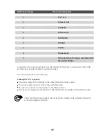
DB-9 Connector pins
Chip card contact points
1
C1 (V c.c.)
2
C2 (reset to 0)
3
C3 (Clock)
4
C4 (reserved)
5
C5 (Ground)
6
C6 (Vpp)
7
C7 (E-S)
8
C8 (reserved)
9
C9 Ground when the chip is commuted with
the Contact Station
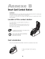
A sequence of commands must be sent via the interface of the printer to insert a card in the printer
and then place it under the Station to establish contact
The command sequence is the following:
Sending the “Sis” sequence
■
One card is moved from the feeder to the Contact Station and stops under it.
■
The card is pushed up to come into contact with the Station.
■
The printer connects the Contact Station to the DB-9 connector.
■
The chip may be programmed via the serial or USB interface of the computer and the external coupler.
Check the Programming Guide of the Dualys printer to obtain more complete information
on how to program a chip card.


