


37
Side Description and Explanation:
1.
Wire Spool Carrier Assembly.
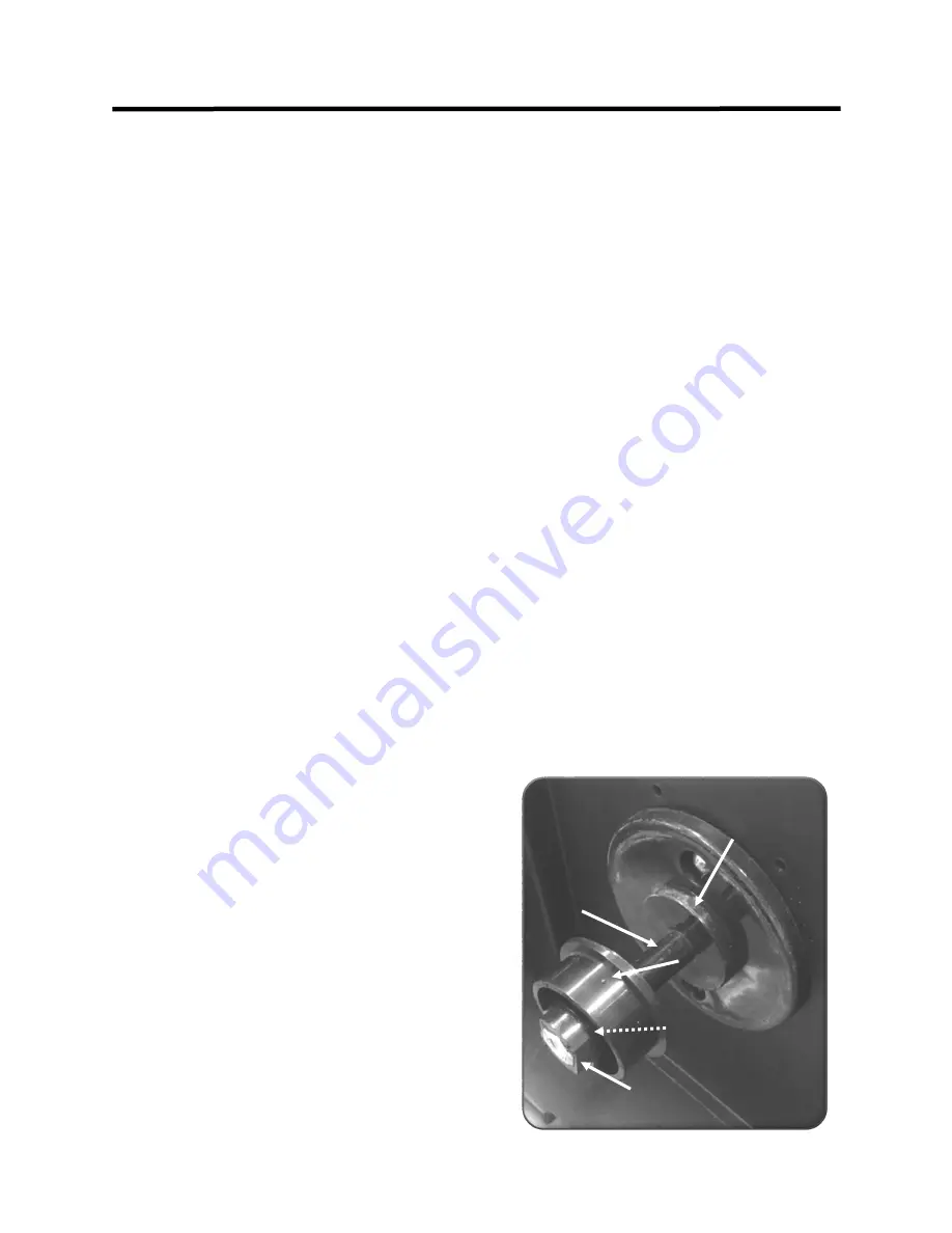
Make note of the
correct assembly order if disassembled.
The or-
der in which they are assembled is important to
be able to provide enough resistance to prevent
de
-
spooling of the wire.
To install remove ten-
sioning nut , spring and collar. Install the spool,
positioning it onto the inside hub shoulder. (See
picture on this page) Hold this in place while
installing the outer hub collar. Install the ten-
sioning spring onto the shaft so that it fits into
the recess on the outer hub collar. Finally, tight-
en the tensioning nut (which compresses the
tensioning spring) so that the wire will not con-
tinue to roll more than one quarter of a turn
after the wire has stopped feeding. Do not tight-
en the tensioning nut to the point that the drive
roller slips or the feeder motor strains while
feeding the wire. The spool carrier assembly
accommodates rolls of wire that are
4”
or
8”
in
diameter. When using
4”
rolls, the roll is sand-
wiched between the two hubs. In order to cen-
ter the wire, the outer hub collar may need to be
reversed.
2.
Polarity.
Note the
“+”
and
“
-
”
symbols located
on the inside of the unit next to the polarity ter-
minals. The unit is shipped with the torch polari-
ty connected to the positive terminal. Positive
polarity is designed to weld with solid wires. To
weld with most Flux
-
core or dual shielded wires,
the polarity must be changed to negative. To
change the polarity to negative, take a Phillips
head screw
-
driver and remove the screw located
on the positive polarity terminal holding the ca-
ble. Place the cable on the negative terminal and
reinstall the screw to retain the cable. Always
remember to alter your work clamp to reflect the
polarity change if using flux core. If the buss bar
is connected to negative, then the work clamp
should be in the
“+”
positive output terminal.
Standard polarity for MIG is
“+”
(DCEP) with the
work clamp in the negative.
Warning: Do not
install work clamp into the AC terminal for MIG!
3.
Wire Feed Assembly.
Note the printed numbers
on the side of the tensioner. These numbers are
a reference point to help properly tension the
wire so that the drive roller will not slip. Do not
over
-
tension the wire because it can create a
condition known as birds nesting. This is where
the wire will tangle up around the feeder and will
if the wire burns back into tip, sticks fast in the
weld puddle or other hard resistance is met. This
will continue to wrap the wire around the drive
mechanism or will jam wire inside the gun liner
until the trigger is released. Considerable effort is
usually needed to clear out a bird
’
s nest condition.
Too little tension will result in regular slipping of
the wire and will cause rapid wear of the drive
components. Do a feed test before beginning a
weld. An occasional cleaning of the feeder mecha-
nism is necessary to prevent wear and damage to
the feeder and to the MIG gun liner. Monitor any
metal flaking and dirt build up that may occur in
the wire feed area. Clean it away gently with com-
pressed air. Also, to improve MIG gun liner service
life, blow out the gun liner with compressed air
regularly to prevent debris accumulation in the
liner. Felt wire lubricators may be bought and used
to keep feeding cleanly while using steel or stain-
less wire.
Do not use heavy weight oil to lubricate
any add
-
on felts.
Do not use harsh cleaners or sol-
vents to maintain the cleanliness of the feeder
mechanism.
When changing wire diamters, don
’
t
forget to change the drive roll sizes (opt.) and the
contact tip size as well.
Depending upon the diam-
eter of the wire used, the MIG gun liner may need
to be changed to work properly. However, the 15
series gun should be able to feed most MIG wire
diameters without requiring a liner change. If trou-
ble is experienced with feeding, purchase a liner
specifically sized for your diameter wire. For steel,
.030”
diameter wire is a good beginning choice for
wire and can span a wide range of settings, greater
than
.023”/.025”
diameter wire. Generally, for
Aluminum,
.035”/.040”
is a better choice for main
for spool gun use than
.025/030”
wire.
Setup Guide and Component Identification
Section 2
Inner Hub Shoulder
Inner Hub Collar
(Note Shoulder Position)
4”
Roll Location
Tensioning Spring
(Hidden from View)
Tensioning Nut
Spool Carrier Assembly.
See item 1 this page.
Содержание POWER MTS 221STi
Страница 38: ...38 REAR VIEW BACK PANEL POWERMTS 221STi Setup Guide and Component Identification Section 2 1 2 4 3 1x220V 6 5...
Страница 44: ...44 MIG OPERATION where porosity and inclusions can be introduced Basic Theory and Function Section 3...
Страница 66: ...66 24 SERIES MIG TORCH OPT Expanded View Basic Theory and Function Section 3...
Страница 72: ...72...


