


14
Setup Guide and Component Identification
Section 2
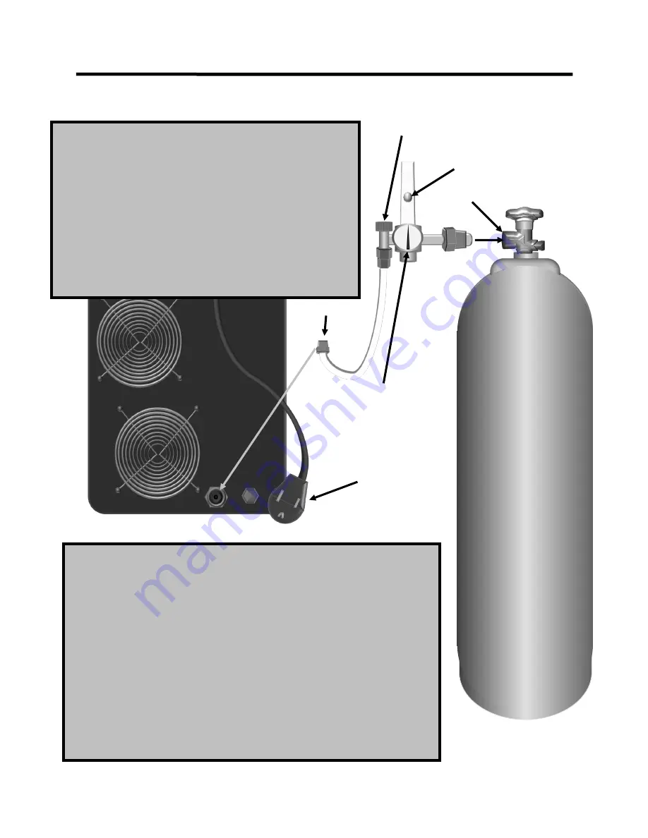
CONNECTIONS AND POLARITY
REAR
580 CGA
5/8”
INERT
NEMA 6
-
50P 50A 240V 1
PHASE
NOTE:
To safely connect the regulator to the cylinder, first make sure the cylinder is
properly chained and secured. Then, before connecting the regulator and while stand-
ing to the side of the cylinder (not in front of the discharge), briefly crack the valve and
allow a 1 to 2 second blast of gas to clear any dirt or contamination from the valve seat.
Then connect the regulator and screw clockwise until finger tight and finish tightening
with a wrench. Do not use a pair of pliers. Make sure the fitting is tight and
slowly
open the valve to check the connection for leaks with luke
-
warm soapy water (or ap-
proved leak detector solution) applied to the fittings at the valve. To connect the hose
to the rear of the unit, connect the
5/8”
gas fitting to the rear, rotating clockwise until
finger tight. Then use
two (2)
wrenches to complete the tightening process. One
wrench should be placed on the female machine side gas inlet nut and should be held
while the other wrench is used to finish tightening the male fitting. Do not tighten with
one wrench or damage to the female nut and fitting may occur (even though the fitting
seems to be tight and secure enough to hold the pressure.) The female side must be
held to prevent rotating in the housing, and stripping of the fitting inside. Check all fit-
tings and connections for leaks once again. Do not use thread tape or sealant on
threads of the unit, regulator or cylinder. These are compression fittings and will tight-
en up once proper pressure has been achieved. If hoses show sign of leaks, tighten
the clamps with a pair of side cutters or end nippers. Simply squeeze the clamp tighter
until the leak stops or add an additional clamp if necessary.
The Ball valve will float briefly once the main cylinder valve is opened and
will then settle down and stop floating after 4 to 5 seconds. Fully open the
cylinder when in use to prevent valve leaks. If the valve continues to float,
you have a leak. Stop and check. To adjust the gas flow rate, the welder
must be turned on. Select MIG or TIG and set post flow to maximum. Gas
flow is actuated by pressing the trigger on the torch (or pedal) and tapping
it. The small knob on top of the down tube that connects to the hose ad-
justs gas flow rate. Screw the valve counter
-
clockwise to increase flow.
This meter will work with both Argon and Argon/CO2 mixes. The rate is
calibrated in Cubic Feet per Hour (CFH) The pressure gauge only con-
firms pressure inside of the tank. The clear plastic tube determines actual
flow rate. As the cylinder looses pressure near the end, flow rate may
need to be readjusted. This is normal. Read the flow rate of the gas at the
middle of the floating ball. Do not open the cylinder valve quickly or dam-
age can occur to the regulator occur over time. Also, do not leave the
regulator on when not in use or loss of cylinder contents may occur over
time. Asphyxiation may occur if leaked cylinder contents flood the area.
ADJUSTMENT VALVE
FLOATING BALL
CYLINDER PRESSSURE
GAUGE
TIG:
For All Metals:
Use 100% Argon
Only or Ar/He mix
No more than 25%
Helium for best arc
starts.
MIG:
Steel: Ar/CO2 Mix,
75/25 or 80/20 for
Short Circuit
Stainless: Various
including 98/2 Ar/
CO2 or Ar/O2 or Tri
-
MIX Blends.
Aluminum: 100%
Argon
Only
Содержание POWER MTS 221STi
Страница 38: ...38 REAR VIEW BACK PANEL POWERMTS 221STi Setup Guide and Component Identification Section 2 1 2 4 3 1x220V 6 5...
Страница 44: ...44 MIG OPERATION where porosity and inclusions can be introduced Basic Theory and Function Section 3...
Страница 66: ...66 24 SERIES MIG TORCH OPT Expanded View Basic Theory and Function Section 3...
Страница 72: ...72...


