Instruction manual for POWERLINE 33 series UPS
2010/06/22
www.ever.eu
6
USER INTERFACE
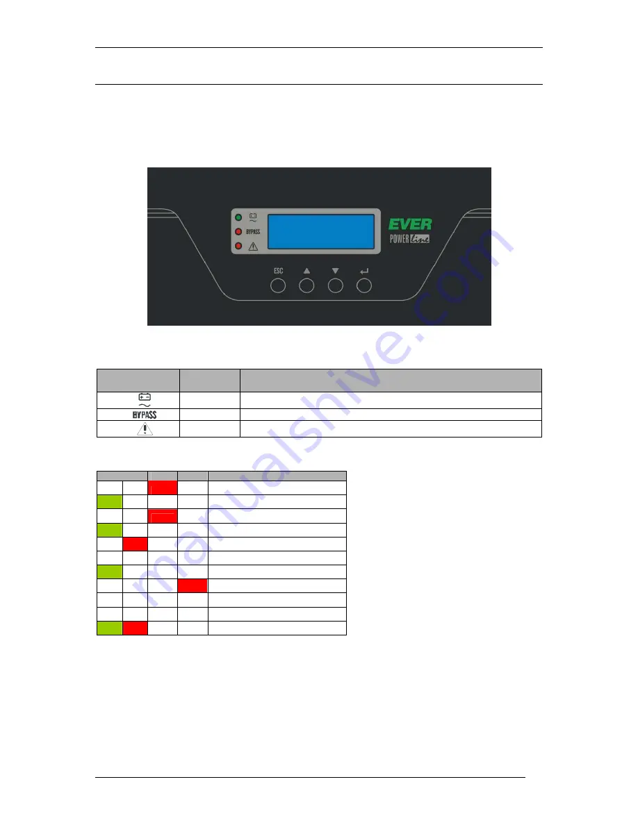
The user interface is a four-button keypad on the upper UPS casing, LCD, and three
LEDs. It allows for the monitoring of the working parameters and their modification.
The use of the interface and the specific parameters are described later on in this
document.
Figure 3: User interface
Table 1 Signalling LEDs
Graphical
symbol
Symbol
Description
LED 1
LED indicating UPS work mode: NORMAL/BACKUP
LED 2
LED indicating the activation of BYPASS
LED 3
LED indicating the EMERGENCY mode
Table. 2 Visual signals (LEDs)
LED 1
LED 2
LED 3
Mode
UNKNOWN
F
NORMAL
ECO
F
BYPASS
BACKUP
F
STANDBY
F
SUSPENDED
E
*
EMERGENCY
F
INIT
F
STOP
*
*
HIBRID
E – if EPO is started, then signals are turned off. Otherwise, emergency
mode signalling is turned on.
F – depends on configuration (none or red).
* - blinking
Содержание POWERLINE 33 10k
Страница 1: ......
Страница 33: ...Instruction manual for POWERLINE 33 series UPS 2010 06 22 www ever eu 33 ...


