background image

Instruction manual for POWERLINE 33 series UPS 

2010/06/22 

www.ever.eu


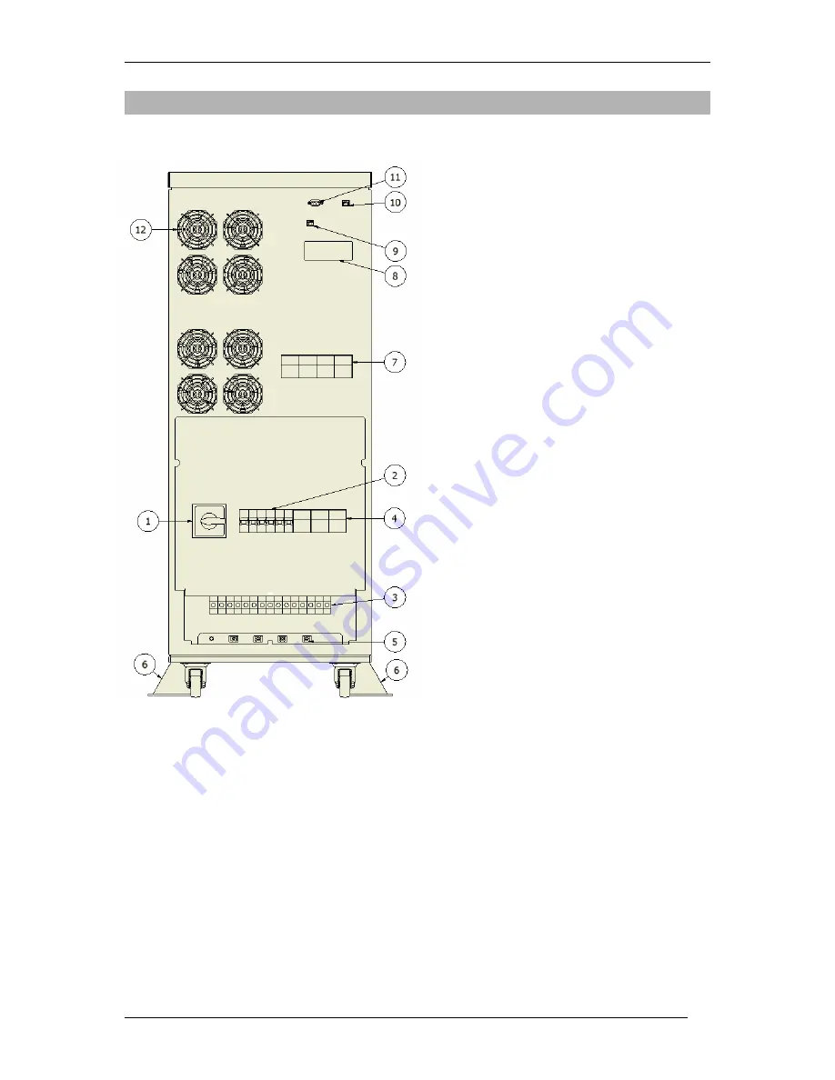
UPS STRUCTURE 


1)  Service bypass circuit 

2)  Input safeguard (F3, F4) 

3)  Input and output sockets 

4)  DC input safeguard (F5) - 

optional 

5)  Cable fixtures 

6)  UPS fixtures 

7)  Internal battery safeguard (F1, 

F2) 

8)  Expansion card slot 

9)  EPO interface 

10) USB port  

11) RS232 port  

12) Fans 


Figure 2: Rear panel 

Содержание POWERLINE 33 10k

Страница 1: ......

Страница 2: ...onnection of modules 27 Disconnection of modules 28 CONNECTING THE UPS 29 Connection Terminals 29 Electric installation 30 START power from mains 31 START no power from mains 31 TURN OFF AND DISCONNECT 32 OPERATION MODES 32 OTHER FUNCTIONAL COMPONENTS 35 Protection 35 EPO 37 MANUAL BYPASS 37 WORK WITH COMPUTERS 38 USB AND RS232 COMMUNICATION 38 SNMP HTTP NETWORK MANAGEMENT CARD 38 Card installatio...

Страница 3: ...e on line VFI class devices that are intended to work with equipment powered from 230V three phase mains POWERLINE 33 units are dedicated to very sensitive receiver devices They generate output voltage with benchmark quality parameters The units feature high short circuit current allowing for the high selectivity of grid protection The units are equipped with an event log that is available to user...

Страница 4: ... The DC bus is the basic power source for the inverter that generates alternating sine wave current that is used to feed the receivers A microprocessor control system ensures the precision and reliability of the entire power supply system An automated bypass system increases the overall system security In the event of inverter failure the current from the mains is provided directly to the load The...

Страница 5: ...STRUCTURE 1 Service bypass circuit 2 Input safeguard F3 F4 3 Input and output sockets 4 DC input safeguard F5 optional 5 Cable fixtures 6 UPS fixtures 7 Internal battery safeguard F1 F2 8 Expansion card slot 9 EPO interface 10 USB port 11 RS232 port 12 Fans Figure 2 Rear panel ...

Страница 6: ...on in this document Figure 3 User interface Table 1 Signalling LEDs Graphical symbol Symbol Description LED 1 LED indicating UPS work mode NORMAL BACKUP LED 2 LED indicating the activation of BYPASS LED 3 LED indicating the EMERGENCY mode Table 2 Visual signals LEDs LED 1 LED 2 LED 3 Mode UNKNOWN F NORMAL ECO F BYPASS BACKUP F STANDBY F SUSPENDED E EMERGENCY F INIT F STOP HIBRID E if EPO is starte...

Страница 7: ...BACKUP beeps that accelerate as the batteries empty until the sound becomes continuous Forced STANDBY two short beeps and a pause EMERGENCY depending on the type of event OVERLOAD continuous sound Short circuit short beeps and pauses 50 50 Overheating slow beeps and pauses 50 50 EPO start beeps and pauses 1 sec 5 sec All LCD pages are based on a tree hierarchy shown in the below figure Figure 4 LC...

Страница 8: ...ciąŜenie Overload F i PrzegrzanieProst Rectifier block overheating A PrzegrzanieProst Rectifier block overheating P i PrzegrzanieFal Inverter block overheating A PrzegrzanieFal Inverter block overheating F i OczekNaLadunekMin Waiting after STANDBY A UszkAkumulatora Damaged batteries P i AkumulatorRozlad 90 s backup time left A EPO Emergency EPO F i Serwis Periodic servicing recommended A BladWewPr...

Страница 9: ...g Once selected a submenu appears that can be navigated by using The arrow on the left side of the submenu name shows the current position The selection must be confirmed by pressing ESC moves one level up POMIARY submenu The POMIARY submenu has two pages with five thematic groups PROSTOWNIK BYPASS WYJSCIE AKUMULATOR TEMPERATURA The menu is navigated similarly to the menu presented above ...

Страница 10: ...n Screen PROSTOWNIK 2 5 3 5 4 5 Description UPS input parameters Type read Parameters PLn rectifier input active power for line n SLn rectifier input apparent power for line n PFLn rectifier input power factor for line n Screen PROSTOWNIK 5 5 Description UPS input parameters Type read Parameters P total rectifier input active power S total rectifier input apparent power f rectifier input frequency...

Страница 11: ...5 Description BYPASS input parameters Type Read Parameters PLn BYPASS input active power line n SLn BYPASS input apparent power line n PFLn BYPASS input power factor line n Per cent value load level for line n Screen BYPASS 5 5 Description BYPASS input parameters Type read Parameters P total BYPASS input active power S total BYPASS input apparent power f BYPASS frequency for line L1 Per cent value...

Страница 12: ...Screen WYJŚCIE 2 5 3 5 4 5 Description UPS output parameters Type read Parameters PLn output active power for line n SLn output apparent power for line n PFLn output power factor for line n Per cent value load level for line n Screen WYJŚCIE 5 5 Description UPS output parameters Type read Parameters P total output active power S total output apparent power f output frequency for line L1 Per cent v...

Страница 13: ...t in cold block Q current battery charge based on current load Tau expected backup duration Screen AKUMULATOR 2 2 Description Battery parameters Type Read Parameters StanAku battery capacity level the value is updated after complete discharge if TestAku is on 100 default means full capacity of batteries Screen TEMPERATURA 1 1 Description Temperature parameters temperature of internal UPS component...

Страница 14: ... are selected with and confirmed with KONTROLA submenu has two types of parameters Some require an additional confirmation to change press or cancellation without change press ESC e g AwaryjneWylaczenie Others are changed by selecting Wl or Wyl with the flag using and confirmed by pressing Once confirmed the page moves up one level in the tree A confirmed parameter is saved in the UPS memory Savin...

Страница 15: ...des Screen KONTROLA 2 4 Description Control flag settings Type read save Parameters Czas Wyl EPO EPO disconnection time 1 minute UPS STB manual switch to STANDBY after predefined period KONFIGURACJA 2 4 Opoz STB ECO switch to ECO mode Screen KONTROLA 3 4 Description Control flag settings Type read save Parameters UPS Bypass manual switch to BYPASS Bypass UPS manual switch to regular mode KasujAwar...

Страница 16: ...ented above UPS parameters can be changed unless the keyboard is locked Pages are selected using and confirmed by pressing Similarly parameters are selected with and confirmed with KONFIGURACJA submenu has numeric parameters The parameters can be increased or decreased using and then confirmed by pressing Once confirmed the page moves up one level in the tree A given change of a parameter can be c...

Страница 17: ...tage limit for BYPASS fDolnyProg minimum frequency limit for main Screen KONFIGURACJA 3 5 Description UPS parameters Type read save Parameters Description UPS parameters Type read save Parameters frequencies for the mains fGornyProg maximum frequency limit for the mains Opoz STB delay when changing to STANDBY after switch by user Poj z STB minimum charge of batteries enabling start up after discha...

Страница 18: ...ternal cells Pr Ladowania total battery charge current Screen ALARMY submenu ALARMY submenu has three pages The menu is navigated similarly to the menu presented above Pages are selected using and confirmed by pressing Alert pages inform about the type of alert that caused EMERGENCY mode ALARMY 1 3 Description UPS alerts Type read Parameters Short circuit short circuit in output during inverter ba...

Страница 19: ... Screen ALARMY 3 3 Description UPS alerts Type read Parameters BladWewProst internal error contact support BladWewFal internal error contact support Screen STATYSTYKA submenu STATYSTYKA submenu has four pages The menu is navigated similarly to the menu presented above Pages are selected using and confirmed by pressing The pages show information on the history of operation STATYSTYKA 1 4 Descriptio...

Страница 20: ...scription Statistics Type Read Parameters Rozladowan number of complete discharge events PrzegrzProst number of events related to rectifier overheating PrzegrzFal number of events related to inverter overheating Screen STATYSTYKA 3 4 Description Statistics Type Read Parameters Przeciaz period of operation with overload Normalna period of operation in NORMAL mode Rezerwowa period of operation in BA...

Страница 21: ...ed using and then confirmed by pressing Once confirmed the page moves up one level in the tree A given change of a parameter can be cancelled by pressing ESC USTAWIENIA PANELU 1 2 Description User interface settings Type read save Parameters Kontrast LCD display contract Podswietlanie LCD display brightness Blok Kl keyboard lock changed in the control software only parameters cannot be changed whe...

Страница 22: ...ed output apparent power P rated output active power VH hardware version VF firmware version VP communication protocol version Screen IDENTYFIKACJA 2 3 Description device information rectifier block Type read Parameters VH hardware version VF firmware version VP communication protocol version Screen IDENTYFIKACJA 3 3 Description Device information inverter block Type read Parameters VH hardware ve...

Страница 23: ...currence OFF means that the causes have ended TYPE Abbreviated description TP NIEZNANY TP INIT TP SIECIOWA TP HYBRYDOWA TP REZERWOWA TP ECO TPSTOP TP CZUWANIE TP STANDBY TP BYPASS Mode TP AWARYJNA A ZwarcieOn ZwarcieOff A PrzeciazenieOn PrzeciazenieOff A PrzegProstOn PrzegProstOff A PrzegFalownikOn PrzegFalownikOff A UszkAkuOn UszkAkuOff A EPOOn EPOOff A BlWewProstOn BlWewProstOff Alerts A BlWewFa...

Страница 24: ...the communication cables in order to avoid potential electric shock when two surfaces of the opposite charge touch the device must be plugged with a PE protective earthing clip failure to comply with this requirement can lead to electric shock It is strictly forbidden for the user to perform any repair work as this would constitute a threat to health and or life All repairs and battery replacement...

Страница 25: ... through the bands affixing it to the pallet Then lift the cardboard boxes off Remove the protective corners NOTE Use extra caution when unboxing as the device has been specially packed Falling of the device may cause a threat to health or life If the device is delivered with batteries please note that it is very heavy see the table of technical parameters Use belts and a hoist to remove the devic...

Страница 26: ...tional assembly fixtures to increase its mechanical stability To do this loosen the 4 M8 screws located in the central bottom part of the device Place the fixtures carefully and screw them to the device by using the previously removed screws Figure 6 Assembly grips Detailed information is provided in a separate installation guidelines document that is enclosed with the product BATTERY PACK optiona...

Страница 27: ...7 Connect the module to the power supply unit pay special attention to proper polarity Modules can be connected in a chain i e connections are made between the power supply unit and the first module and then between the first and second modules between the second and third modules etc The protective earthing cables from each unit are routed to a common point in the switching station of the buildin...

Страница 28: ...ll battery modules by opening the fuse mounts and removing the fuse links 5 Remove the connecting element caps 6 Disconnect the modules The connecting cables must be fully disconnected 7 Secure the connecting elements by screwing the protective cap 8 Activate the safeguards in the switching station of the room building 9 Turn the device on based on the start up procedure Note Remember to set the a...

Страница 29: ...he battery pack optional red pole N neutral pole blue pole protective earthing point connection of a cable with an eyehole connector using M6 screw To connect screw the ends of every cable to the connectors Protect the cables against being pulled out with the clips attached to the holders below the connection terminals Wire sizes specified in the wiring guidelines should be used Conductor ends sho...

Страница 30: ...nce with the type and value of the load connected to the wiring system In extreme cases the different protection parameters of the building and power supply unit s systems may cause the former to be activated more rapidly NOTE The user must place following information on all the network switches that are far from the power supply unit BEFORE WORKING WITH THIS CIRCUIT DISCONNECT THE UNINTERRUPTED P...

Страница 31: ...NTROLA 1 4 UPS Perform steps 5 and 6 only if an additional battery pack is connected Once finished the power supply unit can operate normally START no power from mains Proceed as follows to start a properly connected power unit 1 Verify if F3 and F4 safeguards are set to OFF if not set them to OFF 2 Open fuse mounts F1 F2 3 In mount F1 place an appropriate fuse link do not close 4 In mount F5 plac...

Страница 32: ...e fuse links 5 If the battery packs are connected repeat step 4 for safeguards F1 and F2 for the battery packs 6 Unscrew protective caps from the connecting elements rear panel of the power supply unit and potential modules 7 Disconnect the cables fed from the switchboard power supply unit and modules between modules as well It is forbidden to leave loose end cables unconnected 8 Put the protectiv...

Страница 33: ...Instruction manual for POWERLINE 33 series UPS 2010 06 22 www ever eu 33 ...

Страница 34: ...flag on the unit behaves similarly to OFF LINE units In ECO the outputs are fed from the BYPASS or batteries BACKUP Internal blocks do not participate in power processing and entire unit is more efficient STOP In STOP the power supply unit is turned off logically in interface and there is no current in the mains that would comply with the network criteria It is an indirect mode occurring when swit...

Страница 35: ... switching to BYPASS If the overload exceeds 120 of the nominal power rating the BYPASS mode is switched on immediately The unit remains in BYPASS as long as the overload continues above the predefined limit KONFIGURACJA 4 5 ProgKas Prz Once the overload discontinues the unit attempts to restart five times If they fail the unit switches to EMERGENCY mode In BACKUP the overload causes the unit to s...

Страница 36: ...nnecting switch that can be used during assembly The types of protection are specified in the technical parameters table NOTE It is forbidden to use fuse links other than those listed in the device specification Figure 5 Internal batteries protection The instructions placed in the frame above the safety device informing about the need to maintain an appropriate order when switching in must be comp...

Страница 37: ...e user commands to cancel the alert flag KONTROLA 3 4 KasujAwarieFal and sets the release device as inactive normal position in case of the external initiation of the release It is possible to temporarily lock the EPO function during the assembly of the EPO trip device Then the technician can remove the EPO connector without risking the black out of the receiver devices It may last up to 1 minute ...

Страница 38: ...me RS232 and USB ports are plated to ensure separation from the other unit blocks SNMP HTTP NETWORK MANAGEMENT CARD An EVER network management card is optional and can be installed by the user It is a device that is used to integrate the UPS with the Ethernet type computer network The network card is located in the special slot on the back wall of the UPS The network card enables the user to manag...

Страница 39: ... 30 s to fully discharge the internal batteries 5 Unscrew the metal cover of the card slot 6 Connect the card cable cable is in the card slot 7 Insert the card in the slot 8 Screw the cover on the rear panel 9 Connect safeguard F1 by closing the casing 10 Wait 10 seconds at least 11 Connect safeguard F2 by closing the casing 12 Connect safeguard F5 by closing the casing 13 Set safeguards F3 and F4...

Страница 40: ...m Files PowerSoft Next the operating system will start searching and installing the appropriate drivers In case of Windows Vista the system does not start the automatic driver installation from the selected disc Once the USB cable is connected to the computer in the start menu open the control panel and select system properties On the displayed list of devices find the USB hub branch usually explo...

Страница 41: ...nel application is at usr local powersoft Make sure that the system localisation is Polish to enable Polish diacritical symbols Software update Windows The installer application for Windows features an embedded automatic software updater PowerSoft can check regularly for new versions and notify the user about their availability By default the available updates are verified after the user logs in T...

Страница 42: ...e power rating of the UPS and leading to an overload and UPS shut down It is recommended that the batteries are serviced and controlled by competent personnel who are familiar with that problem and ensuring the required measures of prevention The batteries should be replaced with batteries of the same type and number of cells or modules WARNING Protect the batteries against fire explosive WARNING ...

Страница 43: ...nvironment against the negative effects caused by hazardous materials and components as well as the improper storage and processing of such equipment The Act of 29 July 2005 on Waste Electric and Electronic Equipment Article 22 1 Point 1 2 The crossed out waste container symbol means that in the European Union a used product should be handed over to a special waste handling outlet This concerns bo...

Страница 44: ...use 25 A gG 50 A gG 80 A gG 100 A gG 100 A gG OUTPUT PARAMETERS Output system topology 3P5W Nominal output voltage 400 V Rated current 15 A 29 A 44 A 58 A 73 A Minimum wire section surface area 2 5 mm2 6 mm2 10 mm2 16 mm2 16 mm2 Output line protection Switch disconnector 25 A 50 A 80 A 100 A 100 A ENVIRONMENTAL PARAMETERS Quantity of heat released for nominal work conditions 2 100 BTU 3 300 BTU 5 ...

Страница 45: ...ternal batteries 2 x 32 Internal batteries VRLA 12 V 7Ah or VRLA 12 V 9Ah Permitted total capacity of batteries 2 x 200 Ah Maximum charge current 10A Backup time Depends on the type and number of batteries Maximum battery charge time Depends on the type and number of batteries Internal batteries F1 2x 63 A 440 VDC cylindrical 22x58 GLB Protection External batteries F5 2x 63 A 440 VDC cylindrical 2...

Страница 46: ...e is limited to the repair or replacement of products containing such defects The method for removal of defects shall be determined by the manufacturer The guarantee shall not cover equipment with mechanical damage caused by improper maintenance or use or modified in any way by the user EVER Sp z o o does not provide any guarantees or warranties including the guarantees of fitness for sale or for ...

Отзывы: